
Create panel > Systems > Bones button
Animation menu > Create Bones
Tab panels > Objects tab > Bones IK Chain

Dinosaur character modeled using bones
A Bones system is a jointed, hierarchical linkage of bone objects that can be used to animate other objects or hierarchies. Particularly when animating character models that are a single continuous skin, bones provide a quicker solution for manipulation. Bones can be animated with forward or inverse kinematics, using any of the available IK solvers, or through Interactive or Applied IK.
In gmax bones have several parameters, such as taper and fins, that can be used to define the shape the bone represents. The fins also make it easier to see how the bone is rotating.
For animation, it is very important that you understand the structure of a bone object. Each bone has a pivot point at its base that allows the bone to rotate about its pivot point. It might be useful to think of bones as joints, because it is their pivot placements that matter, more than the actual bone object itself. The bone itself is a visual aid that is drawn lengthwise from its base to its child object. The child object is usually another bone.
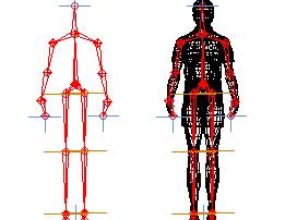
Bones system seen alone and inside a wireframe model, respectively
Any hierarchy can display itself as a bone structure, by simply turning on Bone On/Off in the Object Properties dialog or the Bone Options dialog.
You can create bones by clicking Create Bones, located in the Animation menu or by accessing the Systems panel under the create branch of the command panel.
To create bones do the following.
Your first click in a viewport defines the start joint of the first bone.
The second click in a viewport defines the start joint of the next bone. Visually only 1 bone is drawn at this point because bones are visual aids drawn between two pivot points. It is the actual pivot pointÆs placement that is important.
Each subsequent click defines a new bone as a child of the previous bone. The result of multiple clicks is a single chain of bones.
Right-click to exit bone creation. This will create a small bone at the end of the hierarchy. This bone is used when assigning IK Chains. You may delete the small bone if IK chains are not to be used on the hierarchy.
To create a branching hierarchy, such as legs branching from a pelvis, do the following:
Create a chain of bones and right-click to exit bone creation.
Click Bones again, then click the bone where you want to begin branching. The new chain of bones branches from the bone you click.

A simple chain of three bones
By default, bones are not assigned IK controllers. Assigning IK Controllers, also known as Solvers can be done two ways. Typically you would manually assign IK solvers to a hierarchy of bones after creating them using the IK solvers command on the animation menu. This allows for very precise control over where IK chains are defined.
The second method of assigning an IK solver is more automatic. When you create bones and exit bone creation, an IK solver is automatically applied from the first to last bone created. This is not the default behavior. To enable this option
Turn on Assign to Children if you want to create a bone structure using the IK controller.
See Introduction to Inverse Kinematics.
When you first create a bones system, the position of the bones is the initial state. Before assigning any IK solver or method, you can change the initial state of the bones by moving and rotating the bones individually.
All bones are assigned the color specified for Bones and Link Lines in the Gizmos & Apparatuses section of the Colors panel in the Customize User Interface dialogidh_file_preferences. You can change the color of individual bones by selecting the bone, clicking the active color swatch next to the boneÆs name in the Create panel or Modify panel, and then selecting a color in the Object Color dialog.
Fins are visual aids that help you clearly see a boneÆs orientation. Fins can also be used to approximate a characters shape. Bones have three sets of fins: side, front, and back. By default, fins are turned off.

Bones can now have fins
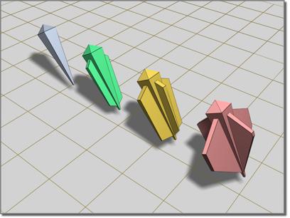
Bones with Fins
You can apply constraints to bones as long as an IK solver or method is not controlling the bones. If the bones have an assigned IK controller, you can constrain only the root of a hierarchy or the goal of the chain.
Procedures
To create a bones system:

 On the Create panel, click Systems, and then click Bones. You can also access Create Bones through the Animation Menu.
Click in a viewport.
This creates a joint that is the base of the bone's hierarchy.
Drag to define the length of the second bone.
Click to set the length of the second bone, and then drag to create the third bone. Drag and click to continue creating new bones.
Right-click to end creation.
The first bone you create is at the top of the hierarchy. The last bone you create is at the bottom. For more about linked objects, see the Hierarchy Panel.
To create a bones hierarchy that uses an IK solver:
In the Create panel, click Systems, and then click Bones.
In the IK Chain Assignment rollout, select an IK Solver from the list. In gmax the IK Limb Solver is the only choice.
Turn on Assign To Children.
In a viewport, click and drag to create the bones. Click twice to create two bones, then right-click to stop bone creation. A third "nub" bone is automatically created when you right-click to stop.
The bones are drawn with an IK solver applied.
To edit the appearance of a bone:
Select a bone.
 Click the Modify tab on the command panel.
Change settings in the Bone Parameters rollout.
To reposition bones in a hierarchy after theyÆve already been created:
Note that repositioning a bone affects its length visually. More importantly, it affects the boneÆs pivot position. The length of the bone is only a visual aid drawn between each boneÆs pivot point. A bone has only one pivot. The bone you see visually is connecting its pivot point to the next boneÆs pivot point.
 In the Hierarchy panel, click Pivot to enter the pivot panel.
In the Adjust Transform rollout, click DonÆt Affect Children.
Move the bone.
Turn off DonÆt Affect Children when you are finished editing the bones.
To add wings to a bone:
Select the bone
In the Modify panel, go to the Bone Parameters rollout and turn on Side Fins.
Adjust the size and appearance of the fins with the appropriate spinner.
Interface
IK Chain Assignment rollout (creation time only)

Provides the tools to quickly create a bone chain with an IK solver automatically applied. Also allows for bone creation with no IK solver.
IK Solver drop-down list: Specifies the type of IK solver to be automatically applied if Assign To Children is turned on. In gmax, the IK Limb Solver is the only available choice.
Assign To Children : When on, assigns the IK solver named in the IK solver list to all the newly created bones except the first (root) bone. When off, assigns a standard PRS Transform controller to the bones. Default=off.
Assign To Root: When on, assigns an IK solver to all the newly created bones including the first (root) bone.
Note: Turning on Assign To Children also automatically turns on Assign To Root.
Bone Parameters rollout (creation and modification time)
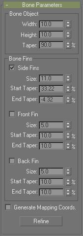
These controls change the appearance of the bones.
Bone Object group
Width: Sets the width of the bone to be made.
Height: Sets the height of the bone to be made.
Taper: Adjusts the taper of the bone shape. A Taper of 0 produces a box shaped bone.
Bone Fins group
Side Fins: Lets you add a set of fins to the sides of the bones you create.
Size: Controls the size of the fin.
Start Taper: Controls the start taper of the fin.
End Taper: Controls the end taper of the fin
Front Fin: Lets you add a fin to the front of the bone you create.
Size: Controls the size of the fin.
Start Taper: Controls the start taper of the fin.
End Taper: Controls the end taper of the fin.
Back Fin: Lets you add a fin to the back of the bone you create.
Size: Controls the size of the fin.
Start Taper: Controls the start taper of the fin.
End Taper: Controls the end taper of the fin.
Generate Mapping Coords: Creates mapping coordinates on the bones. The bones can have materials applied, which can use these mapping coordinates.
Refine button: Allows you to divide a bone into two bones. Turn on Refine, then click a bone. The bone splits in two, with a joint at the location you clicked.
Refine is not available in the Create panel, but is available when you edit bones in the Modify panel.
Object Properties for Bones
In addition to visual properties, bones have behavioral properties. The controls for these are located in the Object Properties dialog. To access a boneÆs object properties, right-click the bone and choosing Properties from the Transform (lower-right) quadrant of the quad menu.
Note: Similar options are available in the Bone Options dialog.
You can use these controls to turn other kinds of objects into bones.
Bone On/Off: When turned on, the bone or object behaves as a bone. Turning this option off causes the node to stop behaving like a bone. There is no auto alignment or stretching. Note that turning this option on doesn't cause the object to immediately align or stretch. However future translations of children may cause rotation and stretching. Default=on for bone objects, off for other kinds of objects.
Auto-Align: When turned off, the boneÆs pivot point doesn't align to its child object. The translation of a child bone will not be converted into rotation of the parent. Instead the child is allowed to move away from the parentÆs X-axis.
Note that changing the state of this check box does not have an immediate visual effect on the skeleton. It only affects future behavior when bones are moved. This option is only available if Bone is off.
Freeze Length: When turned on, the bone maintains its length. When turned off, the boneÆs length is based on the translation of its child bone. This option is available only if Auto-Align is on. Default=on.
Stretch: Determines what kind of stretch takes place. Freeze Length must be off. Default=scale.
None: No stretch takes place.
Scale: Lets the bone scale. The stretch happens along one axis.
Squash: Lets the bone squash. The bone gets fatter as it gets shorter, and thinner as it gets longer.
Axis: Determines the axis used for the stretch.
X/Y/Z: Choose the axis for scaling or squashing.
Flip: Flips the stretch along the selected axis.
Realign: Causes the boneÆs X-axis to realign and point at the child bone (or the average pivot of multiple children). Normally this alignment is maintained, and there is no need to use this option. However it is possible for the bones to come out of alignment by turning off Auto-Align and moving a child bone. Use Realign to realign the bone back to its child.
Reset Stretch: Resets the initial child position used to compute the stretch factor to the current child position. This will cause the stretch factor to become equal to one. If it was previously not equal to one then the object would snap to its original unstretched state. Perform a Reset Stretch operation on the parent of a child bone prior to deleting or unlinking the child.