Generates Gluing Mapping Coordinates using the Duplicate, Extrude, Extrude Along, Lathe, and Twist Along actions.
Note: Before reading on make sure you understand the explanation of the (u,v) coordinate system for maps.

All the tools and actions work by copying the vertex mapping coordinates and then incrementing the v (vertical) mapping coordinate. Normally each will start from a curve or path of vertices. Therefore we have a way of setting vertex coordinates in an curve the tool will create a 2D mapping. Furthermore if we arrange that the u (horizontal) mapping coordinate in the curve (path) varies while the v coordinate is held constant and then hold the u coordinate constant while the tool acts on the v coordinate we will achieve a pretty good 2D mapping. This is because the Extrude or Extrude Along actions almost always acts at right angles to the original curve. This command therefore allow us to assign u mapping coordinates to a path of vertices. (Paths and how to indicate them are already covered elsewhere.)
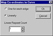
The u map coordinate starts at 0 at the indicated end of the path and increases along the length of the path. There are two ways in which to increment the coordinate, non-linear and linear. Non-linear causes 'u' to increase by 1 for each edge in the path, for example if the path has 5 vertices, the coordinates are 0, 1, 2, 3, and 4. If the edges are different in length then the map images will be scaled differently. Linear scaling causes a fixed number of images to be produced over the length of the curve so that each map is of the same size, thus if you have a curve with 15 edges and you choose 3 copies along the length of the curve, the x mapping coord will be 0.0, 0.2, 0.4 etc., if the edges are different in length the mapping coordinate for each vertex will be calculated so that the maps do not appear distorted.
Linear
Repeat Coordinates

Duplicate - The Duplicate action copies vertex mapping coordinates when vertices are copied. Since moving vertices does not change mapping coordinates, the copied faces will render exactly the same even if the copy is moved or rotated.
Extrude - Extrude creates a copy and then attaches it to the original selected vertices, it therefore copies vertex mapping coordinates (if they exist) as well. There is however one big difference, just copying the vertex mapping coordinates will give a poor looking surface as the new vertices are moved away because the coordinates on one side of the new faces will be exactly the same as on the other. Thus the Extrude tool adds 1.0 to all the v coordinates. This means that the map will go through one cycle from the original vertices to wherever the copy is move to. (Since the extruded vertices are selected, you can use the Apply numeric coordinates command to alter the +1 setting to be anything you like. Note: The u coordinate is unaffected.
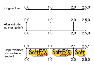
With multiple extrudes you can have the v coordinate extend over a larger surface. But remember what was said above about tiling the image. For example starting with a 4 vertex path, after it is extruded there is no change in v coordinate (vertical direction). When the upper row of vertices have the v mapping coordinate set to 1 each sub-rectangle will show part or all of the map.
Lathe - Because the Lathe action is base on adding a copy, attaching it and rotating it around an axis, its behavior is somewhat similar to that of Extrude the v coordinate is incremented by 0.25 for each section of revolution.
Twist Along - Works like the Extrude Along action.
Extrude Along - If the vertices that are being extruded have mapping coordinates applied, then as the extrusion takes place the v mapping coordinate is incremented. The action dialog has a box to specify the number of copies of the image are to be applied along the extrusion, these will then be scaled linearly.
A typical example of the use of this tools is, make two curves, one to be extruded and the second to be used as the path of the extrusion. Apply mapping coordinates to the first curve using the Map Path Vertices command. Then extrude this curve along the second in the usual way.
Example: Build a Spiral
Start with a polygon primitive having 10 edges. Apply mapping coordinates in a linear mode. Use 6 copies. Create a spiral from the Special functions, move the polygon to the start of the spiral and scale it if necessary. Extrude the polygon along the spiral. Create an appropriate map and "Fix-It" it to the spiral. You can use a patterned map to give the appearance like a coiled-up snake.
Important Note: In this example a closed curve/path was given mapping coordinates. Because the end of the curve is joined back to the start, some faces will have a difference of 5.5 -> 0 in the u mapping across them. The Renderer ignores such a large step and assumes that the mapping coordinates are looping, this looping threshold is 5.0 so that no face should have a difference of more than 5.0 mapping units across any one face. If this rule is violated then the image may not map correctly. If you don't want a loop in the curve, (perhaps because you want the path to proceed in a particular direction) then you should make an open path, but move the two ends so close together that the gap is invisibly small in the final rendering.