Select a spline object. > Modify panel > Modifier List > Patch/Spline Editing > Surface
Select a spline object. > Modifiers menu > Patch/Spline Editing > Surface
Surfaces can be modeled by creating a network of splines (spline cage) and applying the Surface modifier to create a patch surface based on the spline network.
The Surface modifier generates a patch surface based on the contours of a spline network. A patch is created wherever the segments of the interwoven splines form a three- or four-sided polygon. The Surface modifier and the CrossSection modifier, taken together, are referred to as Surface Tools. They allow you to create complex or organic surfaces, like the fuselage of a plane, or a three-dimensional character.
The CrossSection modifier can be applied before the Surface modifier to connect splines representing cross-sections. Once the basic spline network is created and the Surface modifier is applied, the model can be adjusted by editing the splines using an Edit Spline modifier below the Surface modifier in the modifier stack. Since the Surface modifier creates a Patch surface, further refinements can be made to the patch model by adding an Edit Patch modifier above the Surface modifier.
The bulk of the work in using Surface tools to model lies in creating and editing splines in an Editable Spline or Edit Spline modifier. One of the benefits to modeling using splines and Surface Tools is the ease of editing the model. At almost any stage of modeling, you can add a nostril, ear, limb or body by simply adding splines. This lends itself to a free-form approach to organic modeling: you have a mental image of what you want, then you create and edit the spline network until you are satisfied.
Create a spline object.
Make sure that the Spline vertices form valid three-sided or four-sided polygons. Vertices on splines that cross one another should be coincident.
To make spline vertices coincident, drag vertices over each other with 3D Snap turned on. 3D Snap must have the Vertex or End Point option turned on. With 3D Snap turned on, you can snap to vertices on existing splines as you create new splines. You can also select vertices and use the Fuse option in an Editable Spline to make vertices co-incident.
Use the CrossSection modifier to connect spline cross-sections, unless you plan on manually creating the splines that connect the model's cross-sections.
Apply the Surface modifier, then adjust the weld threshold to generate a patch object. Ideally all spline vertices that will form a patch surface are coincident; the Threshold parameter allows patch creation even if vertices are not quite coincident.
Optionally, add an Edit Patch modifier to edit the patch surface.
Tip: Make a reference copy of the spline object, then add the Surface modifier to the copy and edit the original. As you edit the original spline object, patches appear on the reference copy as splines form three-or four-sided shapes. This allows you to view a shaded surface as you model.
You can take this a step further and add a Mirror modifier to the reference copy. As you create splines for one side of a head or body, the reference copy displays an entire model.
There are two primary methods of using the Surface modifier to create patch models.
Create splines that represent a model's cross sections, add the CrossSection modifier to connect the cross sections, and apply the Surface modifier to create the patch surface. This approach works for models like the body of an airplane.
Create a network of splines manually, and then apply the Surface modifier to create the patch surface. This approach works for modeling a face or body of a character.


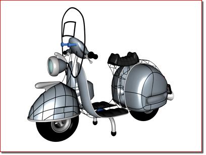
Scooter: Splines form cross sections of the body
One method of using Surface Tools is to create splines that represent a model's cross-sections, then the CrossSection and Surface modifiers are applied to create the patch surface.


Face: Spline network based on front and profile reference images
Two intersecting texture-mapped polygons are used as a reference to create a network of splines manually. Drawing lines on the physical sculpture is used as an added visual aid to position the splines in this case. The CrossSection modifier is not necessary if you create the spline network manually.


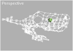
Rhino head: Spline network begins with the profile
In the left image, the head of a rhinoceros is modeled by creating a network of splines. The first spline created is the profile of the rhino; other splines are added and edited to complete the model. In this case, a reference copy of the spline model was created and a Surface modifier was added to the copy.
As the spline network is edited, the patch surface of the reference copy is updated dynamically. This allows you to view a shaded patch model as you manipulate the spline network, any surface anomalies can be spotted and corrected. See the tutorial "Modeling a Rhino Head with Modifiers".

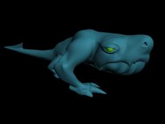
Sequence of images showing the spline network, the patches created by the Surface modifier, and a shaded view of an alien character
Splines are initially created using the tools in Create panel > Shapes > Splines > Object Type rollout, such as Line, Circle and Arc. Splines can also be created using the Create Line command in an Editable Spline or and Edit Spline modifier.
Splines are edited by applying an Edit Spline modifier to the selected spline object or editing parameters in an Editable Spline. Editing splines changes the patch surface created by the Surface modifier.
To add splines to a spline object, use the Attach command in the Edit Spline modifier.
Within a spline object, splines need not be continuous. A spline object may consist of ten splines for example. As long as the spline vertices are coincident, or close enough for the Threshold parameter in the Surface modifier to weld them together, a surface will be generated.
Example: Understanding valid splines:

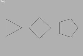
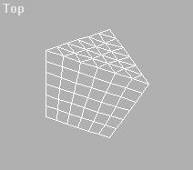
 In the Top viewport, use Create panel > Shape > NGon to create three NGons: a three-sided, four-sided, and five-sided NGon, each about 100 units wide.
 Make sure that all the splines form one object. Do this by applying an Edit Spline modifier to one of the NGons and using Attach to add the remaining NGon objects.
Choose Patch/Spline Editing > Surface from the Modifier List.
Notice that the three- and four-sided splines formed patches but the five-sided Ngon did not. The five-sided spline does not form a three- or four-sided closed polygon. To make it a valid spline, a line must be created to form a three- and four-sided polygon.
In the stack display, choose the Edit Spline modifier again. Turn on Create Line on the Geometry rollout, and create a line that bisects the five-sided NGon.
The start and end points of the line should overlap the vertices on the NGon. Being exact is not critical; the Threshold parameter fuses spline vertices based on their proximity.

In the stack display, choose the Surface modifier again. Now the five-sided NGon is a patch object, consisting of a quad patch and a tri patch.
Note: If the spline object did not turn into a patch, turn up the Surface modifier's Threshold parameter until the patches appear.
Example continued: Adjusting the shape of the spline:
 In the stack display, expand the Edit Spline modifier's hierarchy, and choose the Vertex sub-object level.
In the Top viewport, select the top vertex of the five-sided NGon.
Two vector handles are displayed. These handles can be moved on any axis.
 Turn on Select and Move on the toolbar, then drag the handles around in the Top viewport.
The shape of the spline changes.
 Below the stack display, turn on the Show End Result On/Off Toggle button.
The patch changes shape to fit the spline.


Spline Options group
Threshold: Determines the overall distance that is used to weld the vertices of the spline object. All vertices/vectors within the threshold of each other are treated as one. Threshold uses units set in the Units Setup dialog.
Note: Spline control handles are also treated as vertices, so setting high Threshold levels can produce unexpected results.
Flip Normals: Flips the normal direction of the patch surface.
Remove Interior Patches: Removes interior faces of an object that you would not normally see. These are the faces created within the caps or other interior patches of the same type of a closed polygon.
Use only selected segs: Only segments selected in the Edit Spline modifier will be used by the Surface modifier to create patches.
Note: Segment Sub-Object does not have to be left on in the Edit Spline modifier.
Patch Topology group
Steps: The steps field spinner determines how many steps are used between each vertex. The higher the step count, the smoother the curve you will get between vertices.