
Create panel > Shapes > Splines
Splines include the following object types:
This topic covers aspects of spline creation that are common to all object types, including the parameters available in the General rollout. For parameters unique to a particular spline type, see its section by clicking the appropriate link, above.
Procedures
To control starting new shapes manually:
Turn off the check box next to the Start New Shape button.
Click the Start New Shape button.
Begin creating splines.
Each spline is added to the compound shape. You can tell you are creating a compound shape because all the splines remain selected.
Click Start New Shape to complete the current shape and prepare to start another.
Issues to remember about creating shapes:
You can go back and change the parameters of a shape containing a single spline after the shape is created.
You cannot change the parameters of a compound shape. For example, create a compound shape by creating a circle and then adding an arc. Once you create the arc, you cannot change the circle parameters.
You can add splines to a shape by selecting the shape and then creating splines with the Start New Shape check box off.
To create a spline using keyboard entry:
Click a spline creation button.
Expand the Keyboard Entry rollout.
Enter X, Y, and Z values for the first point.
Enter values in any remaining parameter fields.
Click Create.
Interface
Object Type rollout
AutoGrid: Lets you automatically create objects on the surface of other objects by generating and activating a temporary construction plane based on normals of the face that you click.
For more information, see AutoGrid.
Start New Shape: A shape can contain a single spline or it can be a compound shape containing multiple splines. You control how many splines are in a shape using the Start New Shape button and check box on the Object Type rollout. The check box next to the Start New Shape button determines when new shapes are created. When the box is on, the program creates a new shape object for every spline you create. When the box is off, splines are added to the current shape until you click the Start New Shape button.
Shape Selection buttons: Let you specify the type of shape to create.
Name and Color rollout
Lets you name an object and assign it a viewport color. For details, see Name and Color rollout.
Mesh Settings rollout
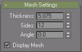
Lets you create a mesh based on the spline. You can also convert the displayed mesh into a mesh object by applying an Edit Mesh modifier or converting to an Editable Mesh.
Thickness: Set this to specify the diameter of the mesh. (Spinner value: float, 0.0 to 1.0E30)
Sides: Sets the number of sides for the spline mesh. For example, a value of 4 will give you a square cross section.
Angle: Adjust the rotational position of the cross-section. For example, if you have a square cross section you can use Angle to position a "flat" side down.
Display Mesh: Displays the mesh in the viewports.
Interpolation rollout

These settings control how a spline is generated. All spline curves are divided into small straight lines that approximate the true curve. The number of divisions between each vertex on the spline are called steps. The more steps used, the smoother the curve appears.
Steps: Spline steps can be either adaptive (that is, set automatically by turning on Adaptive) or specified manually.
When Adaptive is off, use the Steps field/spinner to set the number of divisions between each vertex. The valid range is 0 to 100 steps. Splines with tight curves require many steps to look smooth while gentle curves require fewer steps.
Optimize: When on, removes unneeded steps from straight segments in the spline. Optimize is not available when Adaptive is on. Default=on.
Adaptive: When off, enables manual interpolation control using Optimize and Steps. Default=off.
When on, Adaptive sets the number of steps for each spline to produce a smooth curve. Straight segments always receive 0 steps.

Optimized spline left and adaptive spline right. Resulting wireframe view of each, respectively, on the right.
The main use for manual interpolation of splines is in morphing or other operations where you must have exact control over the number of vertices created.
Creation Method rollout

Many spline tools use the Creation Methods rollout. On this rollout you choose to define splines by either their center point or their diagonal.
Edge: Your first mouse press defines a point on the side or at a corner of the shape and you drag a diameter or the diagonal corner.
Center: Your first mouse press defines the center of the shape and you drag a radius or corner point.
Text and Star do not have a Creation Methods rollout.
Line and Arc have unique Creation Methods rollouts that are discussed in their respective topics.
Keyboard Entry rollout
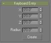
You can create most splines using keyboard entry. The process is generally the same for all splines and the parameters are found under the Keyboard Entry rollout. Keyboard entry varies primarily in the number of optional parameters. The image above shows a sample Keyboard Entry rollout for the Circle shape.
The Keyboard Entry rollout contains three fields for the X, Y, and Z coordinates of the initial creation point, plus a variable number of parameters to complete the spline. Enter values in each field and click the Create button to create the spline.