
Select an editable spline. > Modify panel > Expand the editable spline in the stack display. > Segment sub-object level
Select an editable spline. > Modify panel > Selection rollout > Segment button
Select an editable spline. > Right-click the spline > Tools 1 (upper-left) quadrant of the quad menu > Sub-objects > Segment
A segment is the portion of a spline curve between two of its vertices. While at the Editable Spline (Segment) level, you can select single and multiple segments and move, rotate, and scale them using standard methods.
Procedure
To change segment properties:
Select an editable spline segment, and then right-click.
On the Tools 1 (upper-left) quadrant of the quad menu, choose Line or Curve.
The effect of changing segment properties varies according to the type of vertices at the segment end.
Corner vertices always result in line segments regardless of the segment property.
Smooth vertices can support both line or curve segment properties.
Bezier and Bezier Corner vertices apply their tangent handles only to curve segments. Tangent handles are ignored by line segments.
A tangent handle associated with a line segment displays an X at the end of the handle. You can still transform the handle, but it has no effect until the segment is converted to a curve segment.
Interface
Mesh Settings, Interpolation and Selection rollouts
See Editable Spline for information on the Mesh Settings, Interpolation and Selection rollout settings.
Soft Selection rollout
See Soft Selection Rollout for information on the Soft Selection rollout settings.
Geometry Rollout

Create Line: Adds more splines to the selected spline. These lines are separate spline sub-objects; create them in the same way as the line spline. To exit line creation, right-click or click to turn off Create Line.
PolyConnect: Turn this off if you don't want the new line connected to the endpoint of an existing line. When PolyConnect is on, when creating lines, if the initial mouse click is over an existing endpoint in the shape, the newly created line is automatically attached to that endpoint. This can be an annoyance, especially when creating spline networks for use in Surface Tools.
Break: Lets you specify a break point at any segment in the shape (you do not have to first select a segment). When on, the mouse icon changes to a Break icon. You can now click any spot on a segment. The clicked spot becomes two coincident vertices, and the segment is split into two parts.
Attach: Attaches another spline in the scene to the selected spline. Click the object you want to attach to the currently selected spline object. The object you're attaching to must also be a spline.
For further details, see Attach.
Reorient: Reorients the attached spline so that its creation local coordinate system is aligned with the creation local coordinate system of the selected spline.
Attach Mult.: Click this button to display the Attach Multiple dialog, which contains a list of all other shapes in the scene. Select the shapes you want to attach to the current editable spline, then click OK.
Refine group
The Refine function includes a number of functions useful for building spline networks for use with the Surface Modifier.
Refine: Lets you add vertices without altering the curvature values of the spline. Click Refine, and then select any number of spline segments to add a vertex each time you click (the mouse cursor changes to a "connect" symbol when over an eligible segment). To finish adding vertices, click Refine again, or right-click in the viewport.
You can also click on existing vertices during a refine operation, in which case the software displays a dialog asking if you want to Refine or Connect Only to the vertex. If you choose Connect Only the software will not create a vertex, the software simply connects to the existing vertex.
The Refine operation creates a different type of vertex depending on the types of vertices on the endpoints of the segment being refined.
If the bordering vertices are both Smooth types, the Refine operation creates a Smooth type vertex.
If the bordering vertices are both Corner types, the Refine operation creates a Corner type vertex.
If either of the bordering vertices is a Corner or Bezier Corner, the Refine operation creates a Bezier Corner type.
Otherwise, the operation creates a Bezier type vertex.
Connect: When on, creates a new spline sub-object by connecting the new vertices. When you finish adding vertices with Refine, Connect makes a separate copy of each new vertex and then connects all of the copies with a new spline.
Note: You must turn on Connect before clicking Refine.
After turning on Connect and before beginning the refinement process, turn on any combination of these options:
Linear: When on, makes all segments in the new spline linear by using Corner vertices. When Linear is off, the vertices used to create the new spline are of the Smooth type.
Bind First: Causes the first vertex created in a refinement operation to be bound to the center of the selected segment.
For more information, see Bound Vertex.
Closed: When on, connects the first and last vertices in the new spline to create a closed spline. When Closed is off, Connect always creates an open spline.
Bind Last: Causes the last vertex created in a refinement operation to be bound to the center of the selected segment.
For more information, see Bound Vertex.
Insert: Inserts one or more vertices, creating additional segments. Click anywhere in a segment to insert a vertex and attach the mouse to the spline. Then optionally move the mouse and click to place the new vertex. Continue moving the mouse and clicking to add vertices. A single click inserts a corner vertex, while a drag creates a Bezier (smooth) vertex.
Right-click to complete the operation and release the mouse. At this point, you're still in Insert mode, and can begin inserting vertices in a different segment. Otherwise, right-click again or click Insert to exit Insert mode.
Hide: Hides selected segments. Select one or more segments, and then click Hide.
Unhide All: Displays any hidden sub-objects.
Delete: Deletes any selected segments in the current shape.
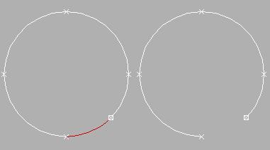
Selected and deleted segment
Divide: Subdivides the selected segment or segments by adding the number of vertices specified by the spinner. Select one or more segments, set the Divisions spinner (to the button's right), and then click Divide. Each selected segment is divided by the number of vertices specified in the Divisions spinner. The distance between the vertices depends on the segment's relative curvature, with areas of greater curvature receiving more vertices.

Selected and divided segment
Detach: Lets you select several segments in various splines and then detach them (or copy them) to form a new shape. Three options are available:
Same Shp: (Same Shape) When on, Reorient is disabled, and a Detach operation keeps the detached segment as part of the shape (rather than producing a new shape). If Copy is also on, you end up with a detached copy of the segment in the same location.
Reorient: The detached segment copies the position and orientation of the source object's creation Local coordinate system. The new detached object is moved and rotated so that its Local coordinate system is positioned and aligned with the origin of the current active grid.
Copy: Copies the detached segment rather than moving it.

Original and detached splines
Display group
Show selected segs: When on, any selected segments are highlighted in red at the Vertex sub-object level. When off (the default), selected segments are highlighted only at the Segment sub-object level.
This feature is useful for comparing complex curves against each other.
Surface Properties rollout
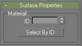
Material group
You can apply different material IDs to spline segments (see Material ID). You can then assign a multi/sub-object material to such splines, which appears when the spline has thickness, or when used for lathing or extrusion. Be sure to turn on Generate Material ID's and Use Shape ID's when lofting, lathing or extruding.
ID: Lets you assign a particular material ID number to selected segments for use with multi/sub-object materials and other applications. Use the spinner or enter the number from the keyboard. The total number of available IDs is 65,535.
Select by ID: Displays a dialog for you to enter a material ID number. Clicking OK selects the segments assigned that material ID. If Clear Selection is on, any previously selected segments are first deselected. If Clear Selection is off, the new selection is added to any previous selection set.