Create or select a spline. > Modify panel > Right-click spline entry in the stack display. > Convert To: Editable Spline
Create or select a spline. > Right-click the spline. > Transform (lower-right) quadrant of the quad menu > Convert To: > Convert to Editable Spline
Editable Spline provides controls for manipulating an object as a spline object and at three sub-object levels: vertex, segment, and spline.
The functions in Editable Spline are the same as those in the Edit Spline modifier. The exception is that when you convert an existing spline shape to an editable spline, the creation parameters are no longer accessible or animatable. However, the spline's interpolation settings (step settings) remain available in the editable spline.
Note: When a spline editing operation (typically, moving a segment or vertex) causes end vertices to overlap, a dialog appears asking if you want to weld the coincident endpoints. Responding in the affirmative causes the overlapping vertices to be welded together.
If you have several modifiers higher in the modifier stack, and want to see the results of edits in an Edit Spline modifier or Editable Spline object, then turn on Show End Result on the Modify panel. As you edit the spline network, you’ll be able to see the result of modifiers above the Editable Spline object. This is useful for Surface Tools work, where you add a Surface modifier above an Editable Spline object in the modifier stack.
See also
Edit Modifiers and Editable Objects
Procedures
To produce an editable spline object, first select the shape, and then do one of the following:
Right-click the shape entry in the stack display and choose Convert To: Editable Spline.
Right-click the object and choose Convert To: > Convert to Editable Spline from the Transform (lower-right) quadrant of the quad menu.
Create a shape with two or more splines by first turning off Start New Shape (on the Create panel). Any shape made up of two or more splines is automatically an editable spline.
Apply an Edit Spline modifier to a shape, and then collapse the stack.
Import a .shp file.
To select shape sub-objects:
Expand the object's hierarchy in the stack display and choose a sub-object level, or click one of the sub-object buttons at the top of the Selection rollout.
You can also right-click the object in the viewports and choose a sub-object level from the quad menu: Tools 1 (upper-left) quadrant > Sub-objects > Choose the sub-object level.
Click a selection or transform tool, and then select sub-objects using standard click or region-selection techniques.
Because sub-object selections can be complex, you might consider using one of the following techniques to prevent clearing the sub-object selection by accident:
Use Lock Selection.
Name the sub-object selection (see Named Selection Sets List).
To clone sub-object selections:
Hold down the SHIFT key while transforming the sub-objects.
You can clone segment and spline sub-objects, but not vertices.
Interface
The following controls are available at the object (top) level and at all sub-object levels.
Mesh Settings and Interpolation rollouts
These creation parameters appear in these rollouts for editable splines. For splines to which the Edit Spline modifier has been applied, creation parameters are available by selecting the object type entry (for example, Circle or NGon) at the bottom of the modifier stack.
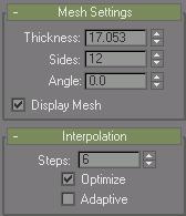
Mesh Settings rollout
Lets you create a mesh based on the spline. You can also convert the displayed mesh into a mesh object by applying an Edit Mesh modifier or converting to an Editable Mesh.
Thickness: Set this to specify the diameter of the mesh. (Spinner value: float, 0.0 to 1.0E30)
Sides: Sets the number of sides for the spline mesh. For example, a value of 4 will give you a square cross section.
Angle: Adjust the rotational position of the cross-section. For example, if you have a square cross section you can use Angle to position a "flat" side down.
Display Mesh: Displays the mesh in the viewports.
Interpolation rollout
The Interpolation controls set how the program generates a spline. All spline curves are divided into small straight lines that approximate the true curve. The number of divisions between each vertex on the spline is called steps. The more steps used, the smoother the curve appears.
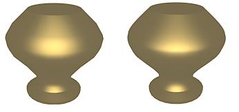
Splines used in above lathed objects contained two steps (left) and 20 steps (right)
Steps: Use the Steps field to set the number of divisions, or steps, the program uses between each vertex. Splines with tight curves require many steps to look smooth while gentle curves require fewer steps. Range=0 to 100.
Spline steps can be either adaptive or manually specified. The method used is set by the state of the Adaptive check box. The main use for manual interpolation is to create splines for morphing or other operations where you must have exact control over the number of vertices created.
Optimize: When on, removes unneeded steps from straight segments in the spline. Default=on.
Note: Optimize is not available when Adaptive is on.

Optimize was used to create spline in the above lathed object.
Adaptive: When on, automatically sets the number of steps for each spline to produce a smooth curve. Straight segments always receive 0 steps. When off, enables manual interpolation control using Optimize and Steps. Default=off.
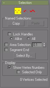
Provides controls for turning different sub-object modes on and off, working with named selections and handles, display settings, and information about selected entities.
When you first access the Modify panel with an editable spline selected, you're at the Object level, with access to several functions available as described in Editable Spline (Object). You can toggle the sub-object modes and access relevant functions by clicking sub-object buttons at the top of the Selection rollout.
You can work with parts of shapes and splines using shape sub-object selection of the Editable Spline object. Clicking a button here is the same as selecting a sub-object type in the Modifier List. Click the button again to turn it off and return to object selection level.
 Vertices define points and curve tangents.
 Segments connect vertices.
 Splines are a combination of one or more connected segments.
Named Selections group
Copy: Places a named selection into the copy buffer.
Paste: Pastes a named selection from the copy buffer.
Lock Handles: Normally you can transform the tangent handles of only one vertex at a time, even when multiple vertices are selected. Use the Lock Handles controls to transform multiple Bezier and Bezier Corner handles simultaneously.
Alike: As you drag the handle of an incoming vector, all incoming vectors of the selected vertices move simultaneously. Likewise, moving the outgoing tangent handle on one vertex moves the outgoing tangent handle for all selected vertices.
All: Any handle you move affects all handles in the selection, regardless of whether they're broken. This option is also useful when working with a single Bezier Corner vertex when you want to move both handles.
SHIFT-click a handle to "break" the tangent and move each handle independently. The Alike option must be chosen to break the tangent.
Area Selection: Lets you select automatically all vertices within a specific radius of the vertex you click. At the Vertex sub-object level, turn on Area Selection, and then set the radius with the spinner to the right of the Area Selection check box. This is useful when using Surface Tools modeling to create a spline cage.
Segment End: Select a vertex by clicking on a segment. In Vertex sub-object, turn on and select a segment close to the vertex that you want selected. Use this when there are a number of coincident vertices and you want to select a vertex on a specific segment. The cursor changes to a cross when it is over a segment. By holding down the CTRL key you can add to the selection.
Select By: Selects vertices on the selected spline or segment. First select a spline or segment in sub-object spline or segment, then turn on vertex sub-object and click Select By and choose Spline or Segment. All the vertices on the selected spline or segment are selected. You can then edit the vertices.
Display group
Show Vertex Numbers: When on, the program displays vertex numbers next to the selected spline's vertices at any sub-object level.
Selected Only: When on, the vertex number or numbers appear only next to selected vertices.
Selection Info
At the bottom of the Selection rollout is a text display giving information about the current selection. If 0 or more than one sub-object is selected, the text gives the number selected.
At the Vertex and Segment sub-object levels, if one sub-object is selected, the text gives the identification numbers of the current spline (with respect to the current object) and of the current selected sub-object. Each spline object contains a spline number 1; if it contains more than one spline, the subsequent splines are numbered consecutively higher.
When a single spline is selected at the Spline sub-object level, the first line displays the identification number of the selected spline and whether it's open or closed, and the second line displays the number of vertices it contains. When more than one spline is selected, the number of splines selected is displayed on the first line, and the total number of vertices they contain is displayed on the second line.
Geometry rollout
The Geometry rollout provides functions for editing a spline object and sub-objects. The functions available at the spline object level (when no sub-object level is active; see Editable Spline (Object)) are also available at all sub-object levels, and work exactly the same at each level. Other functions are also available, depending on which sub-object level is active. Those that apply to other sub-object levels are grayed out.
For specific information, select any of the links below: