Select a mesh or patch object. > Modify panel > Modifier List > Animation Modifiers > Skin
Select a mesh or patch object. > Modifiers menu > Animation Modifiers > Skin
The Skin modifier is a skeletal deformation tool. It allows you to deform one object with another object. Mesh and patch objects can be deformed by gmax bones, splines, or even another object.
After applying the Skin modifier and assigning bones, each bone has a capsule-shaped "envelope." Vertices within these envelopes move with the bones. Where envelopes overlap, vertex motion is a blend between the envelopes.
The initial envelope shape and position depends on the type of bone object. gmax Bones create a linear envelope that extends along the longest axis of the bone geometry. Spline objects create envelopes that follow the curve of the spline. Primitive objects create an envelope that follows the longest axis of the object.
You can also deform the mesh based on the angle of the bones. There are three deformers that allow you to shape the mesh based on bone angles. The Joint and Bulge Angle deformers use a lattice similar to the FFD lattice to shape the mesh at a specific angle. The Morph Angle Deformer morphs the mesh at specified angles. Morph targets are created by using modifiers above the Skin modifier in the stack, or by using the Snapshot command on the main toolbar to create a copy of the mesh and deforming the mesh using standard tools.
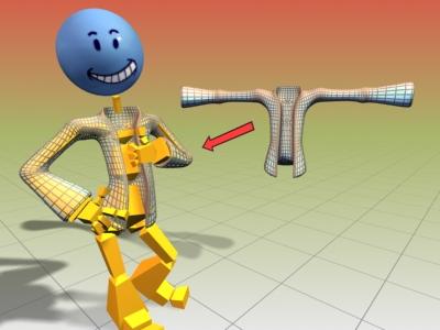
Jacket object deformed using the skin modifier
Procedures
To use the skin modifier:
Prepare the skin (mesh or patch object) and skeleton (bones or other objects). Carefully place the skeleton inside the mesh or patch object so that its elements are be able to influence the polygons or patches in their immediate vicinity.
Select the mesh or patch object and apply the Skin modifier.
Use Add Bones to tell the Skin modifier which objects are to act as skeleton elements.
Use Edit Envelope to modify the volume in which each bone can influence the surrounding geometry.
To adjust the skin and/or bones without affecting the envelopes:
Save the scene.
This is a potentially destructive operation, so it's best not to take any chances with your data.
Select the object to which the Skin modifier is applied.
In the Advance Params rollout, turn off Always Deform.
Apply any necessary transforms to the mesh/patch object or bones objects.
Turn Always Deform back on.
Example: To use the skin modifier to attach a cylinder to a bones hierarchy:

 On the Create panel, under Standard Primitives, click Cylinder.
In the middle of the Top viewport, click and drag 20 units to create the base of the cylinder.
Release the mouse button and drag up 130 units to establish the height of the cylinder.
On the parameters rollout, set Height Segments to 20.
This provides mesh detail for a smooth surface deformation.
 On the Create panel, under Systems, click Bones.
In the Front viewport, click successively three times: below the cylinder, in the middle of the cylinder, and above the top of the cylinder.
Right-click to end Bones creation.
Three bones display. Two of them are within the middle of the cylinder.
 Select the cylinder.
 On the Modify panel, choose Animation Modifiers > Skin from the Modifier List.
On the Skin modifier's Parameters rollout, click Add Bone, and use the Select Bones dialog to select the three bones.
The names of the bones are now displayed in the list.
In the Front viewport, select the bone end effector (IK Chain01) and move it around.
The cylinder deforms to follow the bones. You may have to enlarge the envelopes to encompass all of the cylinder. To adjust envelopes to refine the surface deformation, choose the Skin modifier's Envelope sub-object level, and use the Edit Envelopes controls to resize envelopes and change vertex weights.
Example continued: To use a morph angle deformer:
Create the cylinder and bones from the procedure above before you continue with this procedure.
At frame 50, animate bone 2 so that bones 1 and 2 represent a 90-degree angle.
At frame 0, the bones should be straight at about a 180-degree angle.
Move to frame 0.
Turn on Edit Envelopes in the Parameters rollout.
Select the child bone (bone 2) in the modifiers list of bones.
In the Filters area, turn on Vertices.
In the viewports, region-window select a good portion of the vertices that are controlled by both bones.
In the Gizmo rollout, select the Morph Angle Deformer in the drop-down list and click Add Gizmo.
The Deformer Parameters rollout displays. A base morph target is the first and only target in the list.
Tip: if the Deformer doesn't assign, make sure that bone 2 and not bone 1 is selected in the list.
Scrub the Time Slider to frame 50.
Add an Edit Mesh modifier above the Skin modifier in the modifier stack.
Turn on Vertex and Soft Selection in the Edit Mesh modifier.
Edit the mesh to the shape you want.
Go back down in the stack to the Skin modifier. Answer Yes in the topology warning dialog.
In the Deformer Parameters rollout, click Add From Stack.
A new morph target is added at about 90 degrees.
Delete the Edit Mesh modifier from the stack.
There is a doubling effect of the morph if you don’t delete or deactivate the Edit Mesh modifier.
Scrub the time slider. The mesh morphs as the bone angle changes.
Interface
Tip: Some of the Skin modifier commands are also available from the quad menu.
Modifier Stack
Envelope: Turn on this sub-object level to work on envelopes and vertex weights.
Tip: You can use the quad menu to choose this sub-object level.
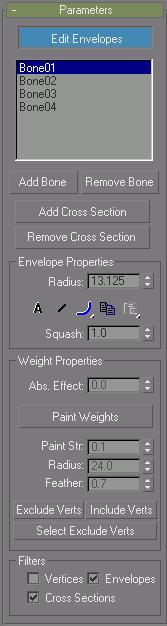
Parameters rollout
Edit Envelope: Turn on this sub-object level to work on envelopes and vertex weights.
List Window: Lists all the bones in the system. Selecting a bone in the list displays that bones envelope and the vertices influenced by the envelope.
Add Bone: Click to add one or more bones from the Add Bones dialog. This is the first step, after applying the modifier to an object.
Remove Bone: Choose a bone in the list, and then click Remove Bone to remove it.
Add Cross Section: Choose a bone in the list, click Add Cross Section, and click a position on the bone in the viewports to add an envelope cross-section.
Remove Cross Section: Select an envelope cross section and click Remove Cross Section to delete it.
You cannot delete the default cross sections. Additional cross sections that you may have added can be deleted.
Envelope Properties group
Radius: Select an envelope cross section, and use Radius to resize it.
Click a cross-section control point to select a cross section. You can also click and drag an envelope cross-section control point in the viewports to resize it.
Absolute: A vertex must merely fall inside the brown outer envelope to have 100% assignment weight to that particular bone. A vertex falling inside more than one outer envelope will be assigned multiple weights summing to 100% based on where it falls in the gradients of each envelope.
Relative: A vertex falling only within an outer envelope will not receive 100% weighting. A vertex must either fall inside two or more outer envelopes whose gradients sum to 100% or greater or the vertex must fall within a red inner envelope to have 100% weight. Any points within a red inner envelope will be 100% locked to that bone. Vertices falling within multiple inner envelopes will receive weighting distributed over those bones.
Envelope Visibility: Determines the visibility of non-selected envelopes. Choose a bone in the list and click Envelope Visibility, then choose another bone in the list. The first bone selected remains visible. Use this to work on two or three envelopes.
Falloff Flyouts: Select a falloff curve for the displayed envelopes. Weight falls off in the area between the inner and outer envelope boundaries if envelopes overlap and Absolute is turned on. Controls here allow you to specify how the falloff is handled.
 Falloff Fast Out: Weight falls of quickly.
 Falloff Slow Out: Weight falls off slowly.
 Falloff Linear: Weight falls off in a linear way.
 Falloff Sinual: Weight falls off in a sinual way.
Copy/Paste: Copies and pastes envelopes. Turn on sub-object Envelopes, choose one bone in the list, click Copy, then choose another bone in the list and click Paste to copy an envelope from one bone to another. Past commands are on a flyout with the following options:
 Paste: Paste the copy buffer to the current selected bone.
 Paste to All Bones: Pastes the copy buffer to all bones in the modifier.
 Paste to Multiple Bones: Pastes the copy buffer to selected bones. A dialog allows you to choose the bones to paste to.
Squash: A squash multiplier for bones that stretch, this is a simple scalar value that reduces or increases the amount of squash applied to a bone when it is stretched with Freeze Length off, and Squash on.
Note: You set Freeze Length and Squash in the Object Properties dialog or in the Bone Options dialog.
Weight Properties group
Abs. Effect: Assign absolute weight for the selected bone to selected vertices.
Choose the Envelope sub-object level, turn on Vertices in the Filters group, select a vertex or vertices, and then use the Abs. Effect spinner to assign weight. Selected vertices move in the viewports as their weight changes.
Paint Weights: Click and brush over the vertices in the viewports to brush on weight for a selected bone.
Paint Str: Sets the brush strength.
Radius: Sets the brush radius.
Feather: Sets the brush falloff.
Exclude Verts: Takes the currently selected vertices and adds them to the exclusion list for the currently selected bone. Any vertices in this exclusion list will not be affected by this bone.
Include Verts: Takes the selected vertices out of the exclusion list for the selected bone. The bone can then affect these vertices.
Select Exclude Verts: Takes the currently excluded vertices and selects them.
Filters group
Selection filters help when you want to work on a particular task, by preventing you from accidentally selecting the wrong item in the viewports.
Vertices: Turn on for vertex selection.
Envelopes: Turn on for envelope selection.
Cross Sections: Turn on for cross-section selection.
Display rollout
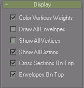
Color Vertices Weights: Displays vertex weight as colors in the viewports.
Draw All Envelopes: Displays envelopes for every bone in the modifier.
Show All Vertices: Draws a small tick at every vertex. On a patch surface, it will also draw all the handles.
Show All Gizmos: Displays all the gizmos in addition to the currently selected gizmo.
Cross Sections On Top: Forces cross sections to be drawn on top of everything.
Envelopes On Top: Forces envelopes to be drawn on top of everything.
Advance Params rollout
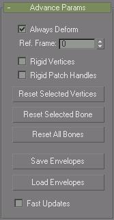
Always deform: A toggle useful for editing the transformation relationship between bones and the controlled points. This relationship is initially set when Skin is applied. To change the relationship the user can deactivate Always Deform, move the object or the bones and reactivate. The new transformation relationship is now used.
Ref. Frame: Sets the frame where the bones and the mesh are in a reference position.
Normally this is frame 0. Start your animation at frame 1 or later if frame 0 is the reference frame. If bones need to be adjusted relative to the mesh, move the time slider to frame 0; turn off Always Deform, move the bones into the correct position and turn on Always Deform.
Rigid Vertices: Causes vertices to have assignments to only one bone as if weighted 100% to the bone whose envelope has the most influence. Vertices will not have weight distributed over more than one bone and the deformation of the skinned object is rigid. This is mainly used for games that do not support weighted point transformation.
Rigid Handles: On a patch model, forces patch handle weights to equal the knots weights.
Reset Selected Vertices: Resets the weight of selected vertices to the envelope defaults. After manually changing vertex weight, use this to reset weights if necessary.
Reset Selected Bone: Resets associated vertex weights back to the original weights calculated for the selected bone's envelope.
Reset All Bones: Resets all vertex weights back to the original weights calculated for all bone's envelopes.
Save/Load Envelopes: Allows you to save the envelope position and shape to disk. If you load envelopes onto a different system of bones, a Load Envelopes dialog prompts you to match the incoming bones to the current bones.
Fast Updates: Turns off viewport display of weighted deformation and gizmos and uses rigid deformation.
Gizmo rollout
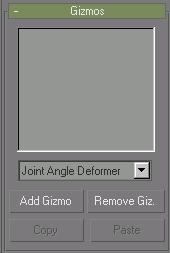
Controls in the Gizmo rollout allow you to deform the mesh according to the angle of the joint, and to add gizmos to selected points on the object. The rollout consists of a list box containing all the gizmos for this modifier, a drop-down list of the current types of gizmos, and four buttons (Add, Remove, Copy and Paste).
The workflow for adding a gizmo is to select the vertices that you want to affect, select the bones that will drive the deformation, and then click the Add button.
There are three available deformers:
The Joint Angle deformer has a lattice that can deform vertices on the parent and child bones.
The Bulge Angle deformer has a lattice that only works on vertices on the parent bone.
The Morph Angle deformer works on vertices of the parent and child bones.
Keep these distinctions in mind when you select vertices to deform. For example, if you want to use the Joint Angle deformer, then select vertices close to the joint that will drive the deformation. If you want the parent bone vertices to deform like a biceps muscle, then select vertices that are only assigned to the parent bone before adding the Bulge Angle deformer. If all the vertices of the parent and child bone must deform, then select all of the vertices and add the Morph Angle deformer.
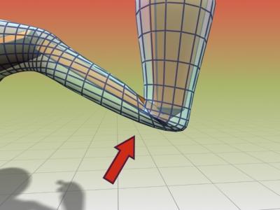
Bending the arm without the morph angle deformer causes the sleeve to crumple.

Using the morph angle deformer creates a smooth bend in the sleeve.
Gizmo List Window: Lists the current Angle Deformers.
The Deformer Parameters rollout changes depending on the type of gizmo selected.
Deformer drop-down list: Lists the available deformers.
Add Gizmo: Adds the current Gizmo to the selected vertices.
To add a gizmo, you must first select the child bone for the joint you want to deform. Then you must select the vertices that you want to deform. You can then add a gizmo.
After a gizmo is added, a Deformer Parameters rollout displays that contains gizmo parameters that you can adjust.
Remove Gizmo: Remove the selected gizmo from the list.
Copy: Copy the selected gizmo.
Paste: Paste the gizmo.
The Paste button pastes the current copy buffer into the currently selected gizmo. You can only paste to like gizmos. For instance, you cannot paste from a bulge gizmo to a joint gizmo.
Deformer Parameters rollout

The following parameters are for the Morph Angle deformer. One way to create morph targets, after the morph gizmo is added, is to add an Edit Mesh modifier to the stack above the Skin modifier. Use the vertex controls in the Edit Mesh modifier to shape the geometry. Then go back in the stack to the Skin modifier and click Add From Stack. You can then delete the Edit Mesh modifier. Add From Stack looks at the last modifier in the stack to get the morph target. Note that when you go back down to the Skin modifier, the morph effect is doubled; this is rectified by deleting or inactivating the Edit Mesh modifier.
Joint Field: Displays the type of Deformer and the associated bone.
List Window: Contains the current morph targets and associated bone angles.
Naming Field: Select a morph target and rename it in this field.
Add from stack: Uses the current state of the stack to get the morph target. Ideally, you have put an Edit Mesh modifier on top of the stack and done your edits before you click Add From Stack.
Add from node: Uses another object as your morph target for this angle. This is like a regular morph target, but instead of being driven by a field, it is driven by the joint angle.
Tip: You can use Snap Shot on the main toolbar to create a new target for morphing.
Delete: Deletes the currently selected morph target from the list.
Enable gizmo: Toggles the effect of the gizmo on and off.
Joint Angle and Bulge Angle parameters
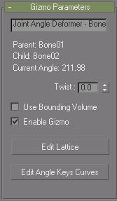
The following parameters are for the Joint Angle and Bulge Angle deformers. These two deformers are almost identical in the way they operate. The difference is that the Bulge Angle deformer only works on vertices of the parent bone, while the Joint Angle deformer works on vertices on both the child and parent bone.
To apply either of these deformers, first select the child link, then select vertices on the mesh, and then apply the deformer. Remember to turn on Vertices in the Filters group before trying to region-select vertices in the viewports.
Once the deformer is applied, turn on Edit Lattice and move the lattice control points in the viewports to deform the mesh at different bone angles.
Name Field: Allows you to change the name of the deformer.
Twist: Allows you to spin the gizmo around the mesh to place control points appropriately.
Use Bounding Volume: Turn this on if you plan to change the geometry, like increasing segments on a cylinder. If the geometry changes, the mesh will still deform inside the lattice if this is turned on.
Enable Gizmo: Toggles the effect of the gizmo on and off.
Edit Lattice: Allows you to move the lattice control points in the viewports.
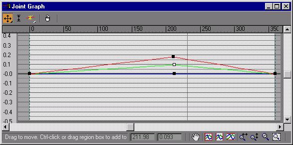
Edit Angle Keys Curves: Brings up a curve editor that lets you manipulate the shape of the lattice at a particular angle. This curve is position vs. angle. It will show you the curves of the current selected points. The red curves are X, Green Y, and Blue Z.