Select an editable poly object. > Modify panel
Select an editable poly object. > Quad menu > Tools 1 quadrant > Sub-Objects sub-menu > Top Level
Editable Poly (Object) functions are available when no sub-object levels are active. These functions are also available at all sub-object levels, and work the same in each mode, except as noted below.
Interface
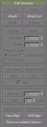
Edit Geometry rollout
Attach: Lets you attach another object in the scene to the selected editable poly. You can attach any type of object, including splines and patch objects. Attaching a non-mesh object converts it to editable-poly format. Click the object you want to attach to the currently selected poly object.
When you attach an object, the materials of the two objects are combined in the following way:
If the object being attached does not have a material assigned, it inherits the material of the object it is being attached to.
Likewise if the object you're attaching to doesn't have a material, it inherits the material of the object being attached.
If both objects have materials, the resulting new material is a multi/sub-object material that includes the input materials. A dialog appears offering three methods of combining the objects' materials and material IDs. For more information, see Attach Options Dialog.
Attach remains active in all sub-object levels, but always applies to objects.
Attach List: Lets you attach other objects in the scene to the selected mesh. Click to display a Select By Name dialog where you choose multiple objects to attach.
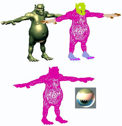
Shaded view of model (upper left); wireframe view of model (upper right); model with objects attached (lower left); and subsequent sub-object material (lower right)
View Align: Aligns all vertices in selected objects to the plane of the active viewport. If a sub-object mode is active, this function affects only selected vertices or those belonging to selected sub-objects. In the case of orthographic viewports, using View Align has the same effect as aligning to the construction grid when the home grid is active. When aligning to a perspective viewport (including camera and light views), the vertices are reoriented to be aligned to a plane that is parallel to the camera's viewing plane. This plane is perpendicular to the view direction that is closest to the vertices' average position.
Grid Align: Aligns all vertices in selected objects to the plane of the current view. If a sub-object mode is active, function aligns only selected sub-objects. This function aligns the selected vertices to the current construction plane. The current plane is specified by the active viewport in the case of the home grid. When using a grid object, the current plane is the active grid object.
Remove Isolated Vertices: Deletes all isolated vertices in the object regardless of the current selection.
Subdivide rollout
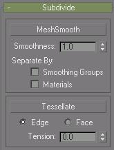
MeshSmooth group
These controls provide explicit MeshSmooth NURMS subdivision for object and sub-object smoothing (see MeshSmooth Modifier).
Smoothness: Determines how sharp a corner must be before polygons are added to smooth it. Smoothness is calculated as the average angle of all edges connected to a vertex. A value of 0.0 prevents the creation of any polygons. A value of 1.0 adds polygons to all vertices even if they lie on a plane.
Separate By Smoothing Groups: Prevents the creation of new polygons at edges between polygons that don't share at least one smoothing group.
Separate By Materials: Prevents the creation of new polygons for edges between polygons that do not share Material IDs.
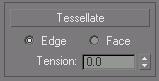
Tessellate group
Use these controls to tessellate (subdivide) selected polygons. Tessellation is useful for increasing local mesh density while modeling. You can subdivide any selection of polygons. Two tessellation methods are available:
Tessellate: Tessellates selected polygons based on the Edge, Face, and Tension (spinner) controls.
Edge: Inserts vertices in the middle of each edge and draws lines connecting those vertices. The number of polygons created will equal the number of sides of the original polygon.
Face: Adds a vertex to the center of each polygon and draws connecting lines from that vertex to the original vertices. The number of polygons created will equal the number of sides of the original polygon.
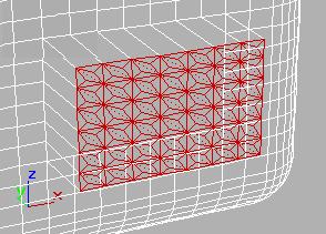
Set of polygons showing face -Center tessellation
Tension: (Active only when Tessellate By Edge is active.) This spinner, below the Tessellate button, lets you increase or decrease the Edge tension value. A negative value pulls vertices inward from their plane, resulting in a concave effect. A positive value pulls vertices outward from their plane, resulting in a rounding effect.
Surface Properties rollout
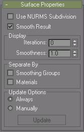
Applies smoothing groups to the object and restricts the MeshSmooth effect by using surface properties.
Use NURMS Subdivision: Provides a display option and weighting controls for use with NURMS objects.
Smooth Result: Applies the same smoothing group to all polygons.
Display group
Iterations: Sets the number of iterations used to smooth the poly object. Each iteration generates all polygons using the vertices created from the previous iteration. Range=0 to 10.
Tip: Be cautious when increasing the number of iterations. The number of vertices and polygons in an object (and thus the calculation time) can increase as much as four times for each iteration. Applying four iterations to even a moderately complex object can take a long time to calculate. You can press ESC to stop calculation and revert to your previous iteration setting.
Smoothness: Determines how sharp a corner must be before polygons are added to smooth it. Smoothness is calculated as the average angle of all edges connected to a vertex. A value of 0.0 prevents the creation of any polygons. A value of 1.0 adds polygons to all vertices even if they lie on a plane.
Separate By group
Smoothing Groups: Prevents the creation of new polygons at edges between faces that don't share at least one smoothing group.
Materials: Prevents the creation of new polygons for edges between faces that do not share Material IDs.
Update Options group
For situations where the complexity of the smoothed object is too high for automatic updates.
Always: Updates the object automatically whenever you change any MeshSmooth settings.
Manually: Turns on manual updating. When manual updating is selected, any settings you change don't take effect until you click the Update button.
Update: Updates the object in the viewport to match the current MeshSmooth settings.
Subdivision Displacement rollout
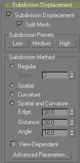
Subdivision Displacement: When on, the program subdivides faces to accurately displace the mesh, using the method and settings you specify in the Subdivision Presets and Subdivision Method group boxes. When off, the program displaces the mesh by moving existing vertices, the way the Displace modifier does. Default=off.
Split Mesh: Affects the seams of displaced mesh objects; also affects texture mapping. When on, the program splits the mesh into individual faces before displacing them; this helps preserve texture mapping. When off, the program uses an internal method to assign texture mapping. Default=On.
Tip: This parameter is required because of an architectural limitation in the way displacement mapping works. Turning Split Mesh on is usually the better technique, but it can cause problems for objects with clearly distinct faces, such as boxes, or even spheres. A box's sides might separate as they displace outward, leaving gaps. And a sphere might split along its longitudinal edge (found in the rear for spheres created in the Top view) unless you turn off Split Mesh.
Subdivision Presets and Subdivision methods groups
The controls in these two groups specify how the program applies the displacement map when Subdivision Displacement is turned on.
Subdivision Presets
Lets you choose a preset low, medium, or high quality surface approximation. While a preset is chosen, the values it uses are displayed on the Subdivision Method rollout.
Low: Selects a (comparatively) low-quality surface approximation. These are the default values:
Viewports, Base Surface:
Method=Spatial and Curvature
Edge=50.0
Distance=50.0
Angle=50.0
Merge=0.0
Advanced Parameters > Minimum=0, Maximum=3
Medium: (The default for both viewports.) Selects a medium-quality surface approximation. These are the default values:
Viewports, Base Surface:
Method=Spatial and Curvature
Edge=20.0
Distance=20.0
Angle=15.0
Merge=0.0
Advanced Parameters > Minimum=0, Maximum=3
High: Selects a high-quality surface approximation. These are the default values:
Viewports, Base Surface:
Method=Spatial and Curvature
Edge=5.0
Distance=15.0
Angle=10.0
Merge=0.0
Advanced Parameters > Minimum=0, Maximum=3
Subdivision Method group
The controls in this group affect the display of the surface in the viewports. Generally speaking, if the preset values you have chosen give good results, you don't need to adjust the controls on this group. Adjust them if you encounter problems with the preset alternative.
Tip: Choose the method that gives the result you need. If you use modifiers heavily, Spatial might be better than Curvature, because of their regular tessellation. Curvature-dependent tessellation can cause problems with some modifiers.
Regular: Generates a fixed tessellation across the surface based on the Steps parameter. Increasing Steps increases accuracy at a cost of speed, and vice versa, but in general this can be the quickest and least accurate way to approximate a surface.
Spatial: Generates a uniform tessellation made of triangular faces.
The Edge parameter specifies the maximum length of a triangular face in the tessellation. The value is a percentage of the object's bounding box. Decreasing this value increases accuracy.
Curvature: Generates a variable tessellation based on the curvature of the surface. The tessellation has a finer grain where the surface is more curved. Changing surface curvature dynamically changes the curvature tessellation.
The Distance parameter specifies how far the approximation can deviate from the actual surface. Distance is a percentage of the diagonal of each surface's bounding box. Each surface in an object is tessellated based on its size, independently of other surfaces. Scaling a surface doesn't change its tessellation. Decreasing this value increases accuracy. When you set Distance to 0.0, the software ignores this parameter and uses the Angle to control accuracy.
The Angle parameter specifies the maximum angle between faces in the approximation. Decreasing this value increases accuracy. When you set Angle to 0.0, the software ignores this parameter and uses Distance to control accuracy.
When both Distance and Angle are 0.0, the surfaces degenerate and can become flat surfaces.
Spatial and Curvature: Combines the spatial (edge-length) method and the curvature (distance and angle) methods, using all three values.
The Edge parameter specifies the maximum length of a triangular face in the tessellation. The value is a percentage of the object's bounding box. Decreasing this value increases accuracy. When you set Edge to 0.0, the effect is equivalent to the Curvature method.
The Distance parameter specifies how far the approximation can deviate from the actual surface. Distance is a percentage of the diagonal of each surface’s bounding box. Each surface in an object is tessellated based on its size, independently of other surfaces. Scaling a surface doesn’t change its tessellation. Decreasing this value increases accuracy. When you set Distance to 0.0, the software ignores this parameter and uses the Edge and Angle values to control accuracy.
The Angle parameter specifies the maximum angle between faces in the approximation. Decreasing this value increases accuracy. When you set Angle to 0.0, the software ignores this parameter and uses the Edge and Distance values to control accuracy.
When Distance, Angle, and Edge are all 0.0, the surfaces degenerate and can become flat surfaces.
View-Dependent When turned on, takes the object's distance from the camera into account while calculating tessellation.
Note: When View-Dependent is on, tessellation quickly reaches the maximum subdivision limit. You might want to increase this value to 7 (the greatest value allowed). See the description of Advanced Parameters, below.
Advanced Parameters: Click to display the Advanced Displacement Approximation dialog. The parameters in this dialog apply to the Spatial, Curvature, and Spatial and Curvature approximation methods.