
Modify panel > Make a selection. > Modifier List > Parametric Modifiers > Displace
Make a selection. > Modifiers menu > Parametric Deformers > Displace
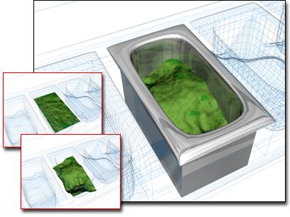
Displace used to change the surface in the container
The Displace modifier acts as a force field to push and reshape an object's geometry. You can apply its variable force directly from the modifier gizmo, or from a bitmapped image. There are two basic ways to use this modifier:
Apply displacement effects directly by setting Strength and Decay values.
Apply the grayscale component of a bitmapped image to generate the displacement. Lighter colors in the 2D image push outward more strongly than darker colors, resulting in a 3D displacement of the geometry.
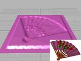

Left: Bitmap displacement on a patch and the bitmap used.
Right: Terrain effects using Displace
Displace distributes its force through four different gizmos: Planar, Cylindrical, Spherical, and Shrink Wrap. Gizmos are also used as mapping coordinates for applying bitmaps. Sphere and Shrink Wrap have the same effect when modeling, but differ in the way they map.
The Spherical and Shrink Wrap gizmos begin with a uniform field around them. The Cylinder and Planar gizmos are both directional. Cylinder pushes at right angles to its axis, and Planar pushes at right angles to its surface.
By default, gizmos are centered on the object. However, you can transform any of these shapes and use it directly as a tool to deform the geometry of an object.
Displace is a versatile modifier with many possible applications. Here are some options:
Produce interior modeling effects by scaling down the gizmo and moving it inside the object. The outward force shapes the geometry from within.
Animate the modeling process. One result is a roving, magnetic-like field that pushes and pulls on a surface.
Add additional Displace modifiers to an object, using each one to create a different modeling effect.
Collapse a finished model into a plain mesh. This reduces the object's complexity and removes all modifiers, but keeps the modeled surface intact.
Procedures
To displace an object:
Select an object and apply the Displace modifier.
In the Parameters rollout > Map group, select one of the four gizmo types.
In the Displacement group, set values for Strength and Decay. Vary these settings to see the effect of the displacement on the object.
Depending on the object and the complexity of the bitmap, you might need to use dense geometry to see the effect clearly. Try a test run and, if necessary, add tessellation in the areas of greatest detail.
To apply a bitmap as a displacement map:
In the Parameters rollout > Displacement group, click the Bitmap button (which is labeled "None" until a map has been chosen). Use the selection dialog to choose a bitmap.
Set the Strength value. Vary the strength of the field to see the effect of the bitmap displacing the object's geometry.
After you get the image you want from bitmapped displacement, you can apply an Optimize modifier to reduce the complexity of the geometry.
To model with the displace modifier:
Apply Displace to the object you want to model. Choose a gizmo on the Map rollout.
Increase the Strength setting until you begin to see a change in the object.
Scale, rotate, and move the gizmo to concentrate the effect. As you do this, adjust the Strength and Decay settings to fine-tune the effect.
Interface
Displacement group
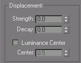
Strength: When set to 0.0, Displace has no effect. Values greater than 0.0 displace object geometry away from the position of the gizmo. Values less than 0.0 displace geometry toward the gizmo. Default=0.0.
Decay: Varies the displacement strength with distance.
By default, Displace has the same strength throughout world space. Increasing Decay causes the displacement strength to diminish as distance increases from the position of the Displace gizmo. This has the effect of concentrating the force field near the gizmo, similar to the field around a magnet repelling its opposite charge. Default=0.0.
Luminance Center: Determines which level of gray Displace uses as the zero displacement value.
By default, Displace centers the luminance by using medium (50 percent) gray as the zero displacement value. Gray values greater than 128 displace in the outward direction (away from the Displace gizmo) and gray values less than 128 displace in the inward direction (toward the Displace gizmo). Use the Center spinner to adjust the default. With a Planar projection, the displaced geometry is repositioned above or below the Planar gizmo. Default=0.5. Range=0-1.0.
Image group
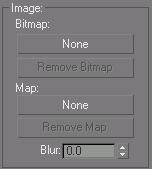
Lets you choose a bitmap and map to use for displacement. Both are assigned and removed in the same way.
Bitmap button: Assigns a bitmap or map from a selection dialog. After you make a valid choice, these buttons display the name of the bitmap or map.
This button is labeled "None" until you choose a map.
Remove Bitmap/Map: Removes the bitmap or map assignment.
Blur: Blurs or softens the effect of the bitmapped displacement by increasing the value.
Map group
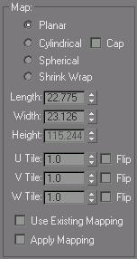
Contains mapping parameters for bitmapped displacement. See UVW Map Modifier.
The four mapping modes control how Displace projects its displacement. The type of Displace gizmo and its location in the scene determine the final effect.
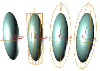
Displace gizmos: Planar, Cylindrical, Spherical, and Shrink Wrap
Planar: Projects the map from a single plane.
Cylindrical: Projects the map as if it were wrapped around the cylinder. Turn on Cap to project a copy of the map from the ends of the cylinder.
Spherical: Projects the map from a sphere, with singularities at the top and bottom of the sphere where the bitmap edges meet at the sphere's poles.
Shrink Wrap: Projects the map from a sphere, as Spherical does, but truncates the corners of the map and joins them all at a single pole, creating only one singularity at the bottom.
Length, Width, Height: Specifies the dimensions of the Displace gizmo's bounding box. Height has no effect on Planar mapping.
U/V/W Tile: Sets the number of times the bitmap repeats along the specified dimension. The default value of 1.0 maps the bitmap exactly once; a value of 2.0 maps the bitmap twice, and so on. Fractional values map a fractional portion of the bitmap in addition to copies of the whole map. For example, a value of 2.5 maps the bitmap two and a half times.
Flip: Reverses the orientation of the map along the corresponding U, V, or W axis.
Use Existing Mapping: Has Displace use the UV mapping set earlier in the stack. This has no effect if the object is not mapped.
Apply Mapping: Applies the Displace UV mapping to the bound object. This lets you apply material maps to the object using the same mapping coordinates as the modifier.
Channel group
Specifies whether to apply the displacement projection to a mapping channel or a vertex color channel, and which channel to use. For more information on these channels, see UVW Map Modifier.
Map Channel: Choose this to specify a UVW channel to use for the mapping, and use the spinner to its right to set the channel number.
Vertex Color Channel: Choose this to use the vertex color channel for the mapping.
Alignment group
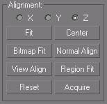
Contains controls for adjusting the mapping gizmo's size, position, and orientation.
X, Y, Z: Flips the alignment of the mapping gizmo along its three axes.
Fit: Scales the gizmo to fit the object's bounding box.
Center: Centers the gizmo relative to the object's center.
Bitmap Fit: Displays a Select Bitmap dialog. The gizmo is scaled to fit the aspect ratio of the bitmap you select.
Normal Align: Turns on Pick mode to let you select a surface. The gizmo is aligned to the normal of that surface.
View Align: Orients the gizmo in the same direction as the view.
Region Fit: Turns on Pick mode to let you drag two points. The gizmo is scaled to fit the specified area.
Reset: Returns the gizmo to its defaults.
Acquire: Turns on Pick mode to let you choose another object and acquire its Displace gizmo settings.