 |
| ||||||||||||||||||||||||||||||


![[Note]](/file/20207/2014.07.ftp.comtrol.com.tar/ftp.comtrol.com/html/images/note.gif) |
|
Insert the wires (12-24 AWG) from the power supply into the terminal block connector contacts.
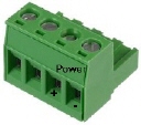
Tighten the wire-clamp screws to prevent the wires from becoming loose.
The RocketLinx ES8105 has a built-in alarm-relay for port link and power events notifications. The relay contacts are normally open and remain open when there is no failure event. The relay contacts will close when there is a failure event to notify.
The failure events are selectable and enabled using the DIP switch on the RocketLinx ES8105.
The relay contacts are rated for a maximum of 1A at 24VDC.

Connect a ground wire between the chassis and earth ground using 12 to 24AWG wire to ensure that the RocketLinx ES8105 is not damaged by noise or electrical shock.
If you are going to mount the RocketLinx ES8105 on a grounded DIN rail, you do not need to also connect the ground wire.
Set the event alarm DIP switch.

Use this table to set the DIP switch for the relay output alarm.
-
Insert the upper end of DIN rail clip into the back of DIN rail track from its upper side.
Lightly push the bottom of DIN rail clip into the track.
Verify that the DIN rail clip is tightly attached on the track.

To remove the RocketLinx ES8105 from the track, reverse the steps above.
Connect standard Ethernet cables between the RocketLinx ES8105 Ethernet ports and the network nodes.
The Fast Ethernet ports support 10BASE-T and 100BASE-TX, full- or half-duplex modes. All of the Fast Ethernet ports automatically detect the signal from the connected devices to negotiate the link speed and duplex mode. Auto MDI/MDIX allows you to connect another switch, hub, or workstation without changing straight-through or crossover cables. Crossover cables cross-connect the transmit lines at each end to the received lines at the opposite end.
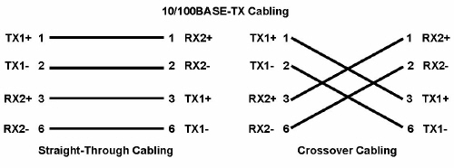
Always make sure that the cables between the switch and attached devices (for example, switch, hub, or workstation) do not exceed 100 meters (328 feet).
If you are installing a RocketLinx ES8105F, connect the fiber port.
The fiber connector is a standard connector or square connector (SC).
|
|
A wrong connection will cause the fiber port not to work properly.
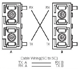
The RocketLinx ES8105 and RocketLinx ES8105F User Guide contains detailed information about the fiber port.
| LED | LED On | LED Blnking | LED Off |
|---|---|---|---|
| PWR 1 | Device powered on | Not applicable | No power |
| Alm (Alarm) | Poer link down or power failure event occurred | Not applicable | Relay not activated or not fault condition has occurred |
Port 1-5 (RocketLinx ES8105) Port 1-4 (RocketLinx ES8105F) | Green: Link, a network device is detected and linked Yellow: Speed, a network device is detected and link esstablished at 100Mbps | Green: Activity, the port is tranmitting or receiving packets from the connected device | Yellow: Speed, a network device is detected and link established at 10Mbps |
Fiber Port 5 RocketLinx ES8105F | Green: Link 100Mbps, the port is operating in full-duplex mode | Green: Activity 100Mbps, the port is tranmitting or receiving packets from the connected device | Port link down or port not connected |
| 06/11/14 | Home | Comtrol Support | |||
| Copyright © 2014 Comtrol Corporation. | ||||