 |
| |||||||||||||||||||||||||||||||||||||||||||||||||||||||||||


| Electrical Specifications | IEEE 802.3af | IEEE 802.3at |
|---|---|---|
|
Power Input Voltage DC1/DC2 | 48VDC (46-57VDC) | 53VDC (50-57VDC) |
|
Power Input Voltage AC and DC1/DC2 aggregated | 53VDC / 8.2A (max) | |
PoE Output Voltage | 44-57VDC | 50-57VDC |
Maximum PoE Power/Port | 15.4W | 32W |
Power Budget DC1 | 400W | |
Power Budget DC2 | 400W | |
Power Budget PSU/AC | 300W | |
Minimum Total Power Budget | Up to 568W | |
Maximum Total Power Budget | Up to 720W | |
Power Consumption | 28W (max.) without PD load | |
![[Note]](/file/20207/2014.07.ftp.comtrol.com.tar/ftp.comtrol.com/html/images/note.gif) |
|
Insert the wires (12 - 22 AWG) from the power supply into the terminal block connector contacts.
Tighten the wire-clamp screws to prevent the wires from coming loose.
The DC1/DC2 LED turns red during the boot cycle and turns green when the unit is ready.
Connect a ground wire between the RocketLinx ES7528 chassis and earth ground using 12-24AWG wire to ensure that the RocketLinx ES7528 is not damaged by noise or electrical shock.
Loosen the earth ground screw on the right side of the RocketLinx ES7510.
Tighten the screw after the earth ground wire is connected.
If desired, connect the Digital or Relay Output. The relay contacts are energized, (open) for normal operation and close for fault conditions. The fault conditions include:
Dry output
Power failure
Link failure
Ping failure
Super ring failure

Mount the RocketLinx ES7528 into a rack.
Attach the brackets to the RocketLinx ES7528 by using the screws provided in the Rack Mount kit.
Mount the RocketLinx ES7528 in a 19-inch rack by using the four rack-mounting screws provided in the kit.
When installing multiple switches, mount them in the rack one below the other. Reserve 0.5U-1U of free space for multiple switches when installing in high temperature environments. It is important to disperse the heat generated by the RocketLinx ES7528.
|
|
Connect standard Ethernet cables between the RocketLinx ES7528 Ethernet ports and the network nodes.
Ports 1-24 are 10/100BASE-TX IEEE802.3af (PoE) and IEEE802.3at (PoE Plus) compliant Ethernet ports. In addition to the 10/100BASE-TX port features, the PoE ports provide 48VDC at 350mA (maximum 15.4W/port) or provide 53VDC at 606mA (maximum 32W/port), auto-sensing and automatic power off when cables are removed. The following table shows the RJ45 PoE pin-out assignment.
| Pin | 10/100BASE-TX PoE |
|---|---|
| 1 | RX+ and Vport- |
| 2 | RX- and Vport+ |
| 3 | TX+ and Vport+ |
| 6 | TX- and Vport+ |
| 4, 5, 7, and 8 | Not connected |
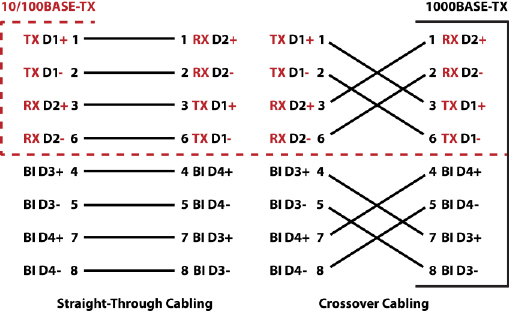
The Fast Ethernet ports (Ports 1-24) support 10BASE-T and 100BASE-TX, full- or half-duplex modes. All of the Ethernet ports auto-detect the signal from connected devices to negotiate the link speed and duplex mode. Auto MDI/MDIX allows you to connect another switch, hub, or workstation without changing straight-through or crossover cables. Crossover cables cross-connect the transmit lines at each end to the received lines at the opposite end.
Ports 25-28 are Gigabit (1000BASE-TX) Combo RJ45/SFP ports.
Always make sure that the cables between the switch and attached devices (for example, switch, hub, or workstation) do not exceed 100 meters (328 feet).
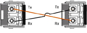
Optionally, connect the SFP transceivers. To ensure system reliability, Comtrol recommends using Comtrol certified SFP transceivers. Cross-connect the transmit channel at each end to the receive channel at the opposite end.
The RocketLinx ES7528 equips four Gigabit SFP ports combined with Gigabit Ethernet ports. The SFP ports supports
1000BASE-SX/LX/LHX/XD/ZX. The SFP ports accept standard mini GBIC SFP transceivers.
|
|
The SFP port does not function until the fiber cable is linked to another active device. When the SFP module is plugged in and there is no active connection (link) on the fiber, then the Gigabit port will link.
The SFP and corresponding RJ45 ports work in an exclusive mode. Traffic sent or received through the SFP module will have priority thus no traffic will be sent or received over the corresponding RJ45 connection. To use the RJ45 connection, remove the corresponding SFP module.
Plug the SFP transceiver into the SFP fiber transceiver.
Connect the transmit channel to the receive channel at each end.
Check the direction/angle of the fiber transceiver and the fiber cable.
Configure the IP address and the RocketLinx ES7528 features using one of the following methods:
Web browser
Telnet
Command line interface (CLI) using the RS-232 console cable
The easiest way to configure the IP address for your network in the RocketLinx ES7528 is to use a Windows host and NetVision (see Programming the IP Address).
The following procedure uses NetVision to program the IP and a web browser to access the RocketLinx ES7528 web management page. For information about using other configuration methods or detailed information about configuring RocketLinx ES7528 features, refer to the RocketLinx ES7528 User Guide.
If necessary, install the latest version of the Java Runtime Environment, which is required to run NetVision and the web management page.
Copy NetVision to a host system with a Windows operating system. Make sure that you note the file location.
Configure the RocketLinx ES7528 IP address for your network.
In NetVision, click the Discovery button, after five seconds the RocketLinx ES7528 should be listed.
To configure a static IP address, double-click the IP Address field and enter a desired IP address.
Double-click the Netmask field and enter a desired subnet mask.
Select the IP Settings --> Modify IP menu item to commit the IP address and Netmask change to the RocketLinx ES7528 switch.
The RocketLinx ES7528 provides both in-band and out-band configuration methods:
Out-band management means that you configure the RocketLinx ES7528 using the RS-232 console cable and the Command Line Interface (CLI) to access the RocketLinx ES7528 without attaching an admin PC to the network. You can also use out-band management, if you lose the network connection to the RocketLinx ES7528.
In-band management means that you connect remotely using the RocketLinx ES7528 IP address through the network. You can remotely connect with the RocketLinx ES7528 Java applet web interface or a Telnet console and the CLI.
If you are planning on using in-band management, you need to program the RocketLinx ES7528 IP address to meet your network requirements. The easiest way to configure the IP address is using a Windows system and NetVision.
The following procedure uses a web browser to configure RocketLinx ES7528 features. Refer to the RocketLinx ES7528 User Guide for other configuration methods.
You can refer to the RocketLinx ES7528 documentation library for additional information.
| 06/11/14 | Home | Comtrol Support | |||
| Copyright © 2014 Comtrol Corporation. | ||||