 |
| ||||||||||||||||||||||||||||||||||||||


| Electrical Specifications | IEEE 802.3af | IEEE 802.3at |
|---|---|---|
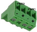
Power Input Voltage DC1/DC2 | 46-57VDC | 50-57VDC |
Maximum PoE Power/Port | 15.4W | 30W |
Total Power Budget DC1/DC2 | 80W: Firmware versions previous to v1.3c 120W: Starting with firmware version v1.3c | |
Power Consumption | 100W (max.) | |
Power Consumption without PD Load | 15W (max.) | |
If desired, connect the digital input (DI) and alarm relay output (DO). The fault conditions can be defined using the RocketLinx ES7510-XT user interface (web page) or Command Line Interface (CLI).
The relay output (DO) and DI contacts are on the terminal block connector on the bottom of the RocketLinx ES7510-XT
The relay contact (DO) supports up to 0.5A at 24VDC. Do not apply voltage and current higher than the specifications. The relay output (DO) is controlled by the pre-defined operating rules. To activate relay output function, refer to the RocketLinx ES7510-XT User Guide.
The Digital Input (DI) accept one external DC type signal input and can be configured to send alert message through Ethernet when the signal is changed. The DI accepts DC type signal and supports isolated input circuit with digital high level input 11VDC to 30VDC and digital low level input 0VDC to 10VDC. Do not apply a higher voltage than the specification; it may cause internal circuit damage or a cause an incorrect DI action.
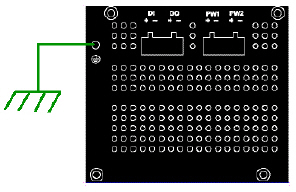 Connect a ground wire between the RocketLinx ES7510-XT chassis and
earth ground using 12-24AWG wire to ensure that the RocketLinx ES7510-XT is not damaged by noise or electrical shock.
Connect a ground wire between the RocketLinx ES7510-XT chassis and
earth ground using 12-24AWG wire to ensure that the RocketLinx ES7510-XT is not damaged by noise or electrical shock.
Loosen the earth ground screw on the right side of the RocketLinx ES7510-XT.
Tighten the screw after the earth ground wire is connected.
Connect a ground wire between the earth ground (surge) screw and earth ground to
provide enhanced surge and lighting immunity.
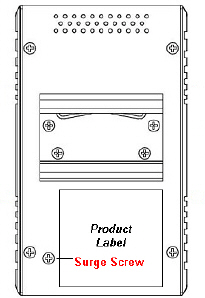
Loosen the earth ground screw located on the back of the unit next to the compliance label.
Tighten the screw after the ground wire is connected.
Make sure that you remove the surge ground screw before insulation/Hi-pot testing.
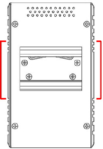
Mount the RocketLinx ES7510-XT to the DIN rail using the clip on the back of the unit or use the wall mounting plate.
Follow the steps below to install the RocketLinx ES7510-XT on a DIN rail:
If necessary, use the screws to attach DIN rail clip to the rear panel of the RocketLinx ES7510-XT. (To remove DIN rail clip, reverse Step 1.)
Insert the upper end of DIN rail clip into the back of DIN rail track from its upper side.
Lightly push the bottom of DIN rail clip into the track.
Verify that the DIN rail clip is tightly attached on the track.
To remove the RocketLinx ES7510-XT from the track, reverse the steps above.
Follow the steps below to install the RocketLinx ES7510-XT with the wall mounting plate:
To remove the DIN rail clip from the RocketLinx ES7510-XT, loosen the screws from the DIN rail clip.
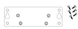
Place the wall mounting plate on the rear panel of the RocketLinx ES7510-XT.
Use the screws to attach the wall mounting plate to the RocketLinx ES7510-XT.
Use the hook holes at the corners of the wall mounting plate to hang theRocketLinx ES7510-XT onto the wall.
To remove the wall mounting plate, reverse the steps above.
Connect standard Ethernet cables between the RocketLinx ES7510-XT ports and the network nodes.
Ports 1-8 are 10/100BASE-TX IEEE802.3af (PoE) and IEEE802.3at (PoE Plus) compliant Ethernet ports.
Ports G9 and G10 are Gigabit combo ports (RJ45/SFP) that support 10/100/1000BASE-TX, 100BASE-FX, and 1000BASE-X with digital diagnostic monitoring (DDM)
The following table shows the RJ45 PoE pin-out assignment.
| Pin | 10/100BASE-TX PoE Signal |
|---|---|
| 1 | RX+ and Vport- |
| 2 | RX- and Vport+ |
| 3 | TX+ and Vport+ |
| 4 and 5 | Not connected |
| 6 | TX- and Vport+ |
| 7 and 8 | Not connected |
All of the fast Ethernet ports auto-detect the signal from connected devices to negotiate the link speed and duplex mode. Auto MDI/MDIX allows you to connect another switch, hub, or workstation without changing straight-through or crossover cables. Crossover cables cross-connect the transmit lines at each end to the received lines at the opposite end.
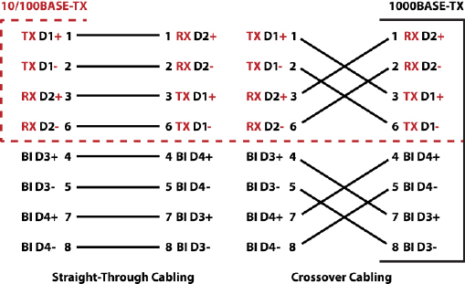
Always make sure that the cables between the switch and attached devices (for example, switch, hub, or workstation) do not exceed 100 meters (328 feet).
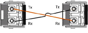
Optionally, connect the SFP transceivers. Cross-connect the transmit channel at each end to the receive channel at the opposite end .
The RocketLinx ES7510-XT two Gigabit SFP ports are combo ports with the Gigabit Ethernet RJ45 ports. The speed of the SFP port supports 100BASE-FX and 1000BASE-X. The SFP ports accept standard mini-GBIC SFP transceivers. To ensure system reliability, Comtrol recommends using Comtrol certified SFP transceivers.
The SFP and corresponding RJ45 ports work in an exclusive mode. Traffic sent or received through the SFP module will have priority thus no traffic will be sent or received over the corresponding RJ45 connection. To use the RJ45 connection, remove the corresponding SFP module.
![[Note]](/file/20207/2014.07.ftp.comtrol.com.tar/ftp.comtrol.com/html/images/note.gif) |
|
The SFP port does not function until the fiber cable is linked to another active device. When the SFP module is plugged in and there is no active connection (link) on the fiber, then the Gigabit port will link.
Plug the SFP transceiver into the SFP fiber transceiver.
Connect the transmit channel to the receive channel at each end.
Check the direction/angle of the fiber transceiver and the fiber cable.
Configure the IP address and the RocketLinx ES7510-XT features using one of the following methods:
Web browser
Telnet
Command line interface (CLI) using the RS-232 console cable
The easiest way to configure the IP address for your network in the RocketLinx ES7510-XT is to use a Windows host and NetVision (see Programming the IP Address).
The following procedure uses PortVision DX to program a static IP address. If you need to configure the RocketLinx ES7510-XT for DHCP you can use one of the other network configuration methods discussed in the RocketLinx ES7510-XT User Guide.
Install PortVision DX on a host system with a Windows operating system.
If you need assistance installing PortVision DX, see the RocketLinx ES7510-XT User Guide.
Start PortVision DX. PortVision DX can be started from Start --> All Programs --> Comtrol --> PortVision DX.
Select the Comtrol product families that you want to locate and click the Scan button.
Configure the RocketLinx ES7510-XT IP address for your network.
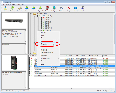
Right-click the RocketLinx ES7510-XT in the Device List pane (lower) that you want to configure and click Properties.
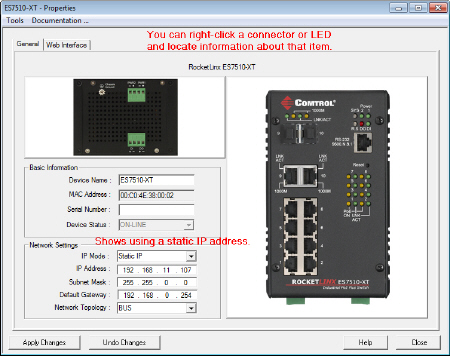
Optionally, enter the RocketLinx ES7510-XT serial number, which displays a friendly device name in the Device List pane on the main page.
Enter an appropriate IP Address for this RocketLinx ES7510-XT.
Optionally, select the appropriate Network Topology, which is an informational field.
You are now ready to configure the RocketLinx ES7510-XT features.
The RocketLinx ES7510-XT provides both in-band and out-band configuration methods:
Out-band management means that you configure the RocketLinx ES7510-XT using the RS-232 console cable and the Command Line Interface (CLI) to access the RocketLinx ES7510-XT without attaching an admin PC to the network. You can also use out-band management, if you lose the network connection to the RocketLinx ES7510-XT.
In-band management means that you connect remotely using the RocketLinx ES7510-XT IP address through the network. You can remotely connect with the RocketLinx ES7510-XT Java applet web interface or a Telnet console and the CLI.
The following procedure uses a web browser to configure RocketLinx ES7510-XT features. Refer to the RocketLinx ES7510-XT User Guide for other configuration methods.
If necessary, install the latest version of the Java Runtime Environment, which is required to run the web management interface.
Open a web browser and enter the IP address of the RocketLinx ES7510-XT.
Enter admin for both the user name and the password when prompted.
Use the web interface to configure your device as needed for your network.
You can refer to the RocketLinx ES7510-XT documentation library for additional information.
| 06/11/14 | Home | Comtrol Support | |||
| Copyright © 2014 Comtrol Corporation. | ||||