 |
| ||||||||||||||||||||||||||||||||||||||||||||||||||||||||||||||||


![[Note]](/file/20207/2014.07.ftp.comtrol.com.tar/ftp.comtrol.com/html/images/note.gif) |
|
Use the following information to wire the power inputs. The required output voltage is 12-24VDC, which delivers IEEE 802.3af PoE on all ports.
|
|
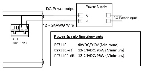
Disconnect the terminal block from the RocketLinx ES7110-VB.
Insert the positive and negative wires (12 to 24 AWG) into the V+ and V- contact on the terminal block connector.
Tighten the wire-clamp screws to prevent the DC wires from becoming loose.
Plug the terminal block into the RocketLinx ES7110-VB.
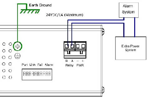
To ensure the system is not damaged by noise or any electrical shock, we suggest that you to make an exact connection between the RocketLinx ES7110-VB and earth ground. On the bottom side of the RocketLinx ES7110-VB, there is one earth ground screw. Loosen the earth ground screw with a screw driver; then tighten the screw after the earth ground wire (12 to 24AWG) is connected.
If you are going to mount the RocketLinx ES7110-VB on a grounded DIN rail, you do not need to also connect the ground wire.
Insert the wires and set the DIP switch using the table (above). After setting the DIP switch to ON, the relay output alarm will detect any power or port failures, and form a short circuit. The alarm relay output is Normal Open.
Set the DIP switch to configure the Port Link Alarm.
The port link failure alarm is applicable when RocketLinx ES7110-VB ports are connected to an auto-negotiation capable 10/100 full-duplex device.
| DIP Switch | Status | Description |
|---|---|---|
| 1 and 2 |
ON OFF |
Enables the Gigabit port link failure alarm for this port. Disables the Gigabit port link failure alarm for this port. |
| 3 through 10 |
ON OFF |
Enables the PoE port link failure alarm for the corresponding port. Disables the PoE port link failure alarm for the corresponding port. |
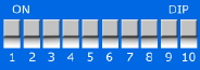
This table provides information about the DIP switch settings for the RocketLinx ES7110-VB.
The RocketLinx ES7110-VB can be mounted on a DIN rail or on a wall panel. The DIN rail clip is already attached to the RocketLinx ES7110-VB at the factory.
The RocketLinx ES7110-VB will disperse heat through the metal case during PoE port operation. The RocketLinx ES7110-VB should be installed and mounted onto a panel which provides good heat dispersion.
You can use this procedure to mount the RocketLinx ES7110-VB on a DIN rail.
Insert the upper end of the DIN rail clip into the back of the DIN rail track from its upper side.
Lightly push the bottom of the DIN rail clip into the track.
Verify that the DIN rail clip is tightly attached to the track.
You can use the following information to connect Ethernet cables between the RocketLinx ES7110-VB ports and the network nodes.
RocketLinx ES7110-VB: Ports G1 and G2 are Gigabit Ethernet uplink ports that support 10BASE-T, 100BASE-TX, and 1000BASE-TX.
Ports 1-8 are Fast Ethernet 10/100BASE-TX PoE ports that are IEEE 802.3af (PoE) compliant (15.4W maximum).
All of the Ethernet ports auto-detect the signal from connected devices to negotiate the link speed and duplex mode. Auto MDI/MDIX allows you to connect another switch, hub, or workstation without changing straight-through or crossover cables. Crossover cables cross-connect the transmit lines at each end to the received lines at the opposite end.
| RJ45 Pin | 10/100BASE-TX PoE (Alternative B) | 1000BASE-TX Gigabit Uplink |
|---|---|---|
| 1 | RX+ | BI_DA+ |
| 2 | RX- | BI_DA- |
| 3 | TX+ | BI_DB+ |
| 4 | Vport+ | BI_DC+ |
| 5 | Vport+ | BI_DC- |
| 6 | TX- | BI_DB- |
| 7 | Vport- | BI_DD+ |
| 8 | Vport- | BI_DD- |
Always make sure that the cables between the switch and attached devices (for example, switch, hub, or workstation) do not exceed 100 meters (328 feet).
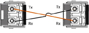
You can use this infrormation to connect the Fiber ports.
The RocketLinx ES7110F-VB provides two Gigabit SFP fiber ports that support up to 1000BASE‐SX/LX (Single or Multi Mode). The SFP ports accept standard MINI GBIC SFP transceivers. For ensure system reliability, Comtrol recommends using Comtrol certified Gigabit SFPs.
Connect the SFP transceiver by plugging the cable into SFP fiber transceiver fist. Cross‐connect the transmit channel at each end to the receive channel at the opposite end as illustrated in the figure.
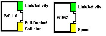
You can this table for information about the LEDs.
| Port Status | Description |
|---|---|
| PoE 1-8 Link/Activity | Green: The port is connected Blinking: Transmitting or receiving packets Off: The port link is inactive |
| PoE 1-8 Full-Duplex/Collision | Yellow: Full-duplex mode connection Blinking: Data collision Off: The link is inactive or operating in half-duplex mode |
| PoE 1-8 Full-Duplex/Collision | Green: Transmitting or receiving packets Blinking: The port link is inactive Off: |
| PoE 1-8 Full-Duplex/Collision | Yellow: Full-Duplex mode connection Blinking: Data collision Off: The link is inactive or operating in half-duplex mode |
| G1/G2 Speed | Green: The port is connected Blinking: Transmitting or receiving packets Off: The port link is inactive |
| G1/G2 Speed | Yellow: Full-duplex mode connection Blinking:
Off: The link is inactive |
| Gigabit Fiber Link/Activity | Green: The port is connected to another fiber port Blinking: Fiber port is transmitting or receiving packets Off: The fiber link is inactive |
| Gigabit Fiber Speed | Yellow blinking: 3 blinks per cycle - 100Mbps Off: The fiber link is inactive |
| 06/11/14 | Home | Comtrol Support | |||
| Copyright © 2014 Comtrol Corporation. | ||||