 |
| ||||||||||||||||||||||||||||||||||||||||||||||||||||||||||||||||||||||||||||||||||||||||||||||||||||||||||||||||||||||||||||||||||||


![[Note]](/file/20207/2014.07.ftp.comtrol.com.tar/ftp.comtrol.com/html/images/note.gif) |
|
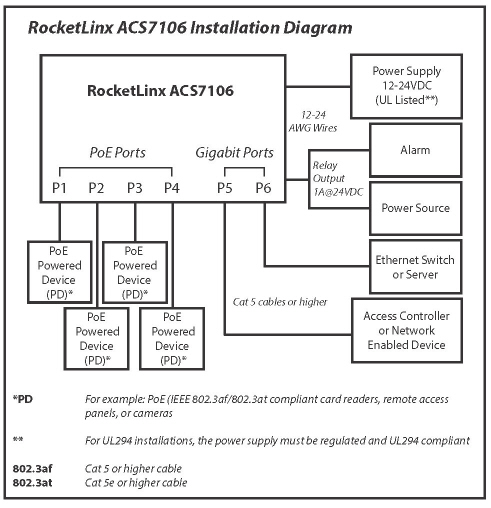
The RocketLinx ACS7106 is compliant with the IEEE802.3af/802.3at PoE standards to deliver a maximum of 30W per port. The total PoE power budget for the RocketLinx ACS7106 in UL294 installations is 90W and 100W in non-UL294 applications.
| Electrical Specifications | Value | |||||
|---|---|---|---|---|---|---|
| Number of Ports | Four 10/100BASE-TX PoE Two 10/100/1000BASE-TX Uplink | |||||
| Power Input | 12-24VDC - | |||||
| Power Consumption (WIthout PD Loading) | 700mA @ 12VDC 350mA @ 24VDC | |||||
| Power Consumption (With PD Loading) | 6.8A @ 12VDC 4.8A @ 24VDC 4.5A @ 24VDC (UL294) | |||||
| Output/Power PoE Port (Maximum) | 30W | |||||
| Standard PoE Voltage | @ ACS7106 output ports | 52-54.3VDC | ||||
| Standard PoE Voltage | 100m* Cat5e @30W (24AWG) | 47-49VDC | ||||
| Standard PoE Voltage | 100m* Cat5e @30W (26AWG) | 44.5-46VDC | ||||
* At the end of the specified distance.
| ||||||
| Total PoE Power Budget | UL294 installation (VIN=24VDC | 90W | ||||
| Total PoE Power Budget | UL294 installation (VIN=12VDC | 60W | ||||
| Total PoE Power Budget | Non-UL294 installation (VIN=24VDC | 100W @ operating temperature -40° to 50°C 90W @ operating temperature 50° to 55°C | ||||
| Total PoE Power Budget | Non-UL294 installation (VIN=12VDC | 60W @ operating temperature -40° to 55°C | ||||
| Operating Temperature | -40° to 55°C 0° to 49°C (UL294) | |||||
| Storage Temperature | -40° to 85°C | |||||
| Operating Humidity | 0° to 95% | |||||
|
|
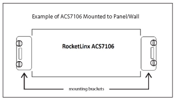
Use the following procedure to install the RocketLinx ACS7106.
-
Make sure that you use appropriate screws when securing the RocketLinx ACS7106.
In UL294 installations, #8 self-tapping screws can be used to mount the RocketLinx ACS7106. Use one or two screws on each side to mount the RocketLinx ACS7106.
-
The RocketLinx ACS7106 must be tied to earth ground to ensure the system meets EMC/EMI requirements.
Using a screw driver, loosen the earth ground screw on the side of the RocketLinx ACS7106 and then tighten the screw after the earth ground wire (12-14AWG) is connected.
-
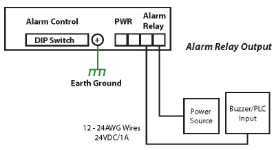
The RocketLinx ACS7106 has a 6-pin DIP switch located on the side panel to configure the alarm relay output. The DIP switch number corresponds to the PoE and Gigabit port numbers.
Note If a port is not connected, make sure that the corresponding DIP switch remains in the OFF position so that the alarm is not activated.
-
The power supply input range is 12-24VDC with a maximum power consumption of 8W without PoE PD loading. Wiring methods shall be compliant with National Electrical Code/NFPA 70/ANSI.
Note Power should be disconnected from the power supply before connecting it to the switch. Otherwise, your screwdriver blade can inadvertently short your terminal connections to the grounded enclosure.

Note For UL installations, the RocketLinx ACS7106 is intended to be used with a regulated UL Listed Class 2 or LPS (Limited Power Supply).
For the highest specified PoE output load, the ACS 7106 is intended to be used with a regulated UL Listed Class 2 or LPS rated at:
24VDC @ 4.8A or 12VDC @ 6.8A, minimum. (UL60950 Installation)
24VDC @ 4.5A or 12VDC @ 6.8A, minimum. (UL294 Installation)
Disconnect the power terminal block from the RocketLinx ACS7106.
Insert the positive and negative wires into PWR+ and PWR- contacts.
Tighten the wire-clamp screws to prevent the wires from being loosened.
Insert the wires and set the DIP switch (above). After setting the DIP switch to ON, the relay output alarm will detect any power or port failures, and form a short circuit. The alarm relay output is Normal Open.
Connect the appropriate Ethernet cables between the RocketLinx ACS7106 Ethernet ports and the network nodes.
Ports 1-4 are Fast Ethernet (10/100BASE-TX) PoE that support IEEE 802.3af/802.3at (PoE+)
Ports 5-6 are Gigabit (10/100/100BASE-TX)
Half and full-duplex connections are supported with auto-negotiated link speed and duplex mode. Auto MDI/MDIX enables direct connection of another hub or switch without the need for crossover cabling. Link/Act LEDs are lit to indicate traffic and link status.
Note The RocketLinx ACS7106 is to be connected to PoE networks without routing to outside the plant.
RJ45 Pin 10/100BASE-TX PoE (Alternative B) 1000BASE-TX Gigabit Uplink 1 RX+ BI_DA+ 2 RX- BI_DA- 3 TX+ BI_DB+ 4 Vport+ BI_DC+ 5 Vport+ BI_DC- 6 TX- BI_DB- 7 Vport- BI_DD+ 8 Vport- BI_DD- 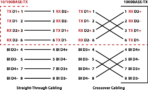
Always make sure that the cables between the switch and attached devices (for example, switch, hub, or workstation) do not exceed 100 meters (328 feet).
This table provides LED information.
| LED | LED On | LED Blnking | LED Off |
|---|---|---|---|
| PWR - Green | System power ready | Not applicable | System not ready |
| PoE (P1-P4) - Green | Valid PoE output and PoE PD is powered | Active PoE | Not applicable |
| Link/Act (P1-P6) - Green | Port on | Port active | Port link down or port not connected |
| ALM - Red | Relay is active and contacts have been shorted | Not applicable | Relay not activated or not fault condition has occurred |
| 06/11/14 | Home | Comtrol Support | |||
| Copyright © 2014 Comtrol Corporation. | ||||