Your are a civil engineer working for the state department of transportation. You have been assigned responsibility for the design of a truss bridge to carry a two-lane highway across the river valley shown below.
Satisfy all of the specifications listed below, while keeping the total cost of the project as low as possible.
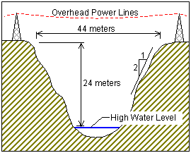
- The bridge may cross the valley at any elevation from the high water level to 24 meters above the high water level.
- If the elevation of the bridge is below 24 meters, excavation of the river banks will be required to achieve the correct highway elevation. (The amount of excavation required at each deck elevation is determined automatically by the West Point Bridge Designer 2010.)
- To provide clearance for overhead power lines (shown above), the highest point on the bridge may not exceed an elevation 32.5 meters above the high water level (8.5 meters above the top of the river banks).
- The bridge may consist of either standard (simple supports) or (arch supports). If necessary, the bridge may also use one intermediate , located near the center of the valley. If necessary, the bridge may also use cable , located 8 meters behind one or both abutments.
- Each main truss can have no more than 50 and no more than 120 .
-
The bridge will have a flat, reinforced deck. Two types of concrete are available:
- Medium-strength concrete requires a deck thickness of 23 centimeters (0.23 meter).
- High-strength concrete requires a deck thickness of 15 centimeters (0.15 meter).
- In either case, the deck will be supported by transverse spaced at 4 meter intervals. (See Component Parts of a Truss Bridge for more information about these terms.) To accommodate these floor beams, your must have a row of joints spaced 4 meters apart at the level of the deck. These joints are created automatically when you begin a new design.
- The bridge deck will be 10 meters wide, such that it can accommodate two lanes of traffic.
- Materials. Each member of the truss will be made of either carbon steel, high-strength low-alloy steel, or quenched and tempered steel.
- . The members of the truss can be either solid bars or hollow tubes. Both types of cross-sections are square.
- Member Size. Both cross-sections are available in a variety of standard sizes.
The bridge must be capable of safely carrying the following loads:
- Weight of the deck.
- Weight of a 5-cm thick , which might be applied at some time in the future.
- Weight of the steel floor beams and supplemental bracing members (assumed to be 12.0 applied at each deck-level joint).
- Weight of the main trusses.
-
Either of two possible truck loadings:
-
Weight of one standard H20-44 truck loading
per lane, including appropriate allowance for the dynamic effects of the moving
load. (Since the bridge carries two lanes of traffic, each main truss must safely
carry one H20-44 vehicle, placed anywhere along the length of the deck.)
- Weight of a single 660 kN Permit Loading (based on the standard H20-44 truck loading), including appropriate allowance for the dynamic effects of the moving load. (Since the Permit Loading is assumed to be centered laterally, each main truss must safely carry one-half of the total vehicle weight, placed anywhere along the length of the deck.)
-
Weight of one standard H20-44 truck loading
per lane, including appropriate allowance for the dynamic effects of the moving
load. (Since the bridge carries two lanes of traffic, each main truss must safely
carry one H20-44 vehicle, placed anywhere along the length of the deck.)
The bridge will comply with the structural provisions of the 1994 LRFD Bridge Design Specification (Load and Design), to include:
- Material densities
- Load combinations
- Tensile strength of members
- Compressive strength of members
The cost of the design will be calculated using the following cost factors:
-
Material Cost:
Carbon steel bars - $3.78 per kilogram
Carbon steel tubes - $6.30 per kilogram
High-strength steel bars - $4.62 per kilogram
High-strength steel tubes - $7.03 per kilogram
Quenched and tempered steel bars - $5.70 per kilogram
Quenched and tempered steel tubes - $7.95 per kilogram
- Connection Cost: $300.00 per joint
- Product Cost: $1000.00 per product
-
Site Cost:
Reinforced concrete deck (medium strength) - $4,000 per 4-meter panel
Reinforced concrete deck (high strength) - $5,000 per 4-meter panel
Excavation - $1.00 per cubic meter (See the Site Design Wizard for excavation volume)
Supports (abutments and pier) - Cost varies (See the Site Design Wizard for specific values)
- $15,000 per anchorage