last changes: 28.11.2004 ps
>>> IDEfile - A ProFile Emulator <<<
What's that?
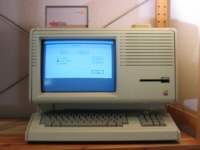
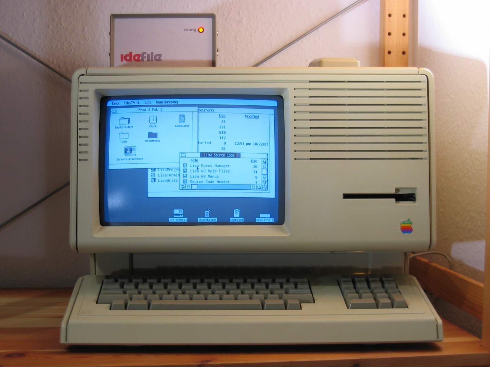
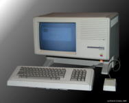 In January 1983, Apple Computer Inc. introduced the Lisa. A $9.995 machine that required more than 200 man-years of hard work and more than $50 million in development costs, and that revolutionized the personal computer market. It was the first commercial sytem with a graphical user interface (GUI) that used a "mouse" as an input device, overlapping "windows" to display data, and pull-down menus. Though Lisa itself was not a real success - Apple sold only 60.000 units until it was discontiunued and replaced by the Macintosh product line - this interface became a standard to almost all operating systems we know today.
Many Lisas are still alive today, they are maintained by hobbyists and collectors. One of the biggest problems for most users is getting hold of a working hard disk drive for their machine. Back in the '80s, Lisa was sold with two types of hard disk systems: the ProFile, an external 5MB drive that could be used with an Apple II, Apple /// or a Lisa, and the Widget, an internal 10MB drive that was fitted into the Lisa 2/10. The reliability of these drives was acceptable in these days, but today most of them have retired :-(. This forces the value of the remaining units in orders of magnitude that are far from reasonable and quite unaffordable for most users :-(((.
A Lisa Emulator Project can be found on the net, but up to now hardly any working ProFile emulators are known. Years ago, Sun Remarketing and Sigma Seven offered ProFile-compatible hard drives. Tom Stepleton and Al Bui tried to design a bridge from the ProFile parallel interface to an EPP printer port, letting a PC emulate the drive. Project documentation can be found here(NOTA JPL:dead link?), but after their prototype refused to work, they abandoned the project. Therefore I decided to design and build my own drive.
IDEfile is a ProFile compatible hard drive for Apple /// and Lisa systems. Emulation of the classic 5MB ProFile and the rare ProFile 10M is provided. I intend to support Widget_10 and a big 20MB Widget_20 too, but before that I have to figure out the syntax of its additional commands. Any help on this is appreciated, also any technical information on calibrating and formatting these beasts!
How does it work?
IDEfile employs an IDE hard disk to store its data. I wanted to use components that could be used with a machine from the early '80s without getting red in the face (no FPGAs, no ARM7 cpu, ...), but some trade-offs towards modern technology had to be made. A 80C31 microcontroller executing about 1800 lines of assembler code and two GALs control the system. The use of a CF card in True IDE mode instead of the IDE drive should also be possible, however I cannot recommend this. LisaOS writes about 30 blocks just to load the Envrionments Window, therefore the 100.000 write cycles of a flash card would be consumed very soon.
Depending on the size of the hard disk, up to eight volumes (partitions) are supported. From the host's point of view, each volume is a different hard disk, but only one can be accessed at the same time. Each volume could be of the following types:
| Type 0: |
ProFile |
5MB ($2600 blocks) |
| Type 1: |
ProFile 10M |
10MB ($4C00 blocks) |
| Type 2: |
Widget_10 |
10MB ($4C00 blocks, not yet) |
| Type 3: |
Widget_20 |
20MB ($9800 blocks, not yet) |
A block has a size of 532 bytes. Therefore two sectors on the disk are used, the space required on the hard disk is two times the volume size. IDEfile does not care about the number of bytes sent or read by the host, as long as it is below 1024 bytes.
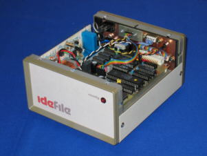
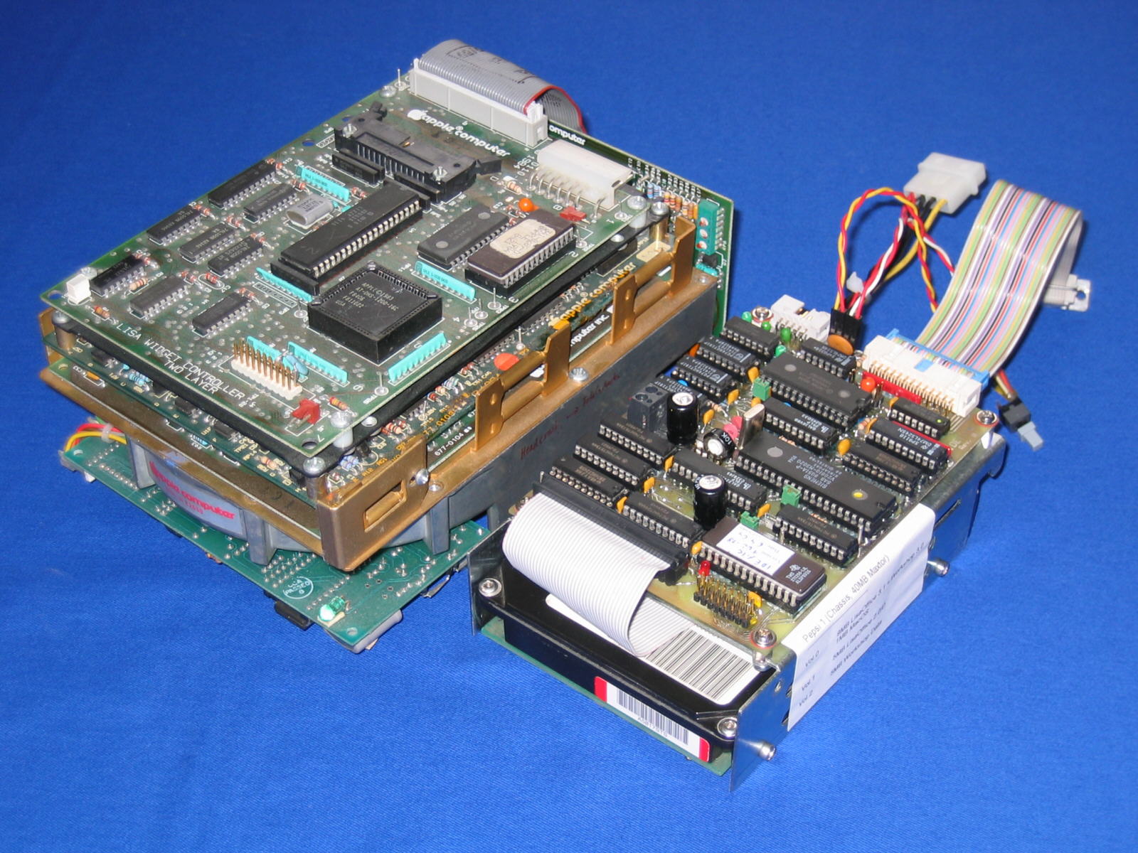
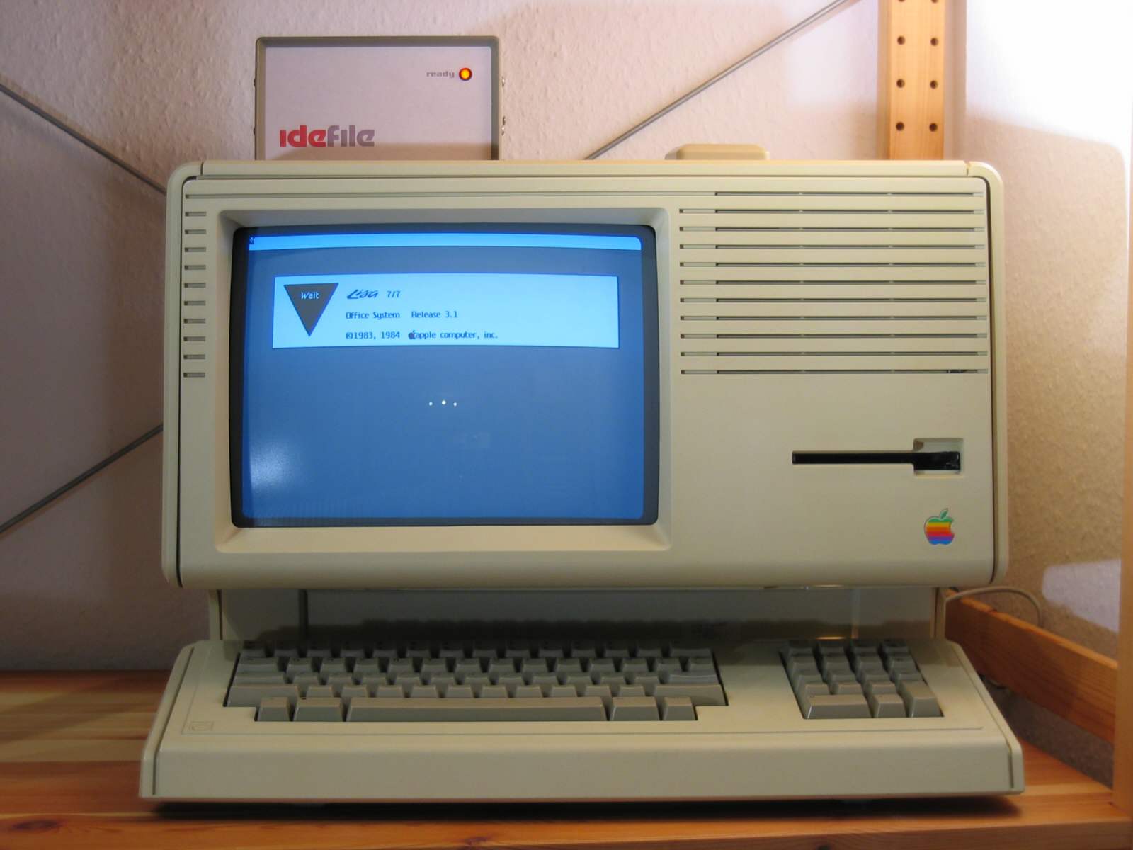
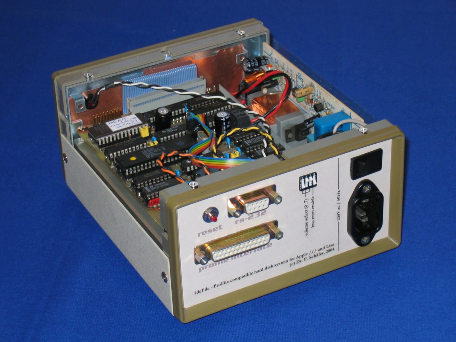
IDEfile's PCB has a size of approximately 100mm x 140mm, this is the same size as a 3,5" hard disk. It can be mounted on the back of the drive, resulting in a compact unit which can be fitted into Lisa's hard drive cage or into a seperate box. The pictures below show these two alternatives. For maximum flexibility, many different operating controls are provided:
- Three DIP switches to select the active volume. These switches are read only once after the selftest procedure, therefore the Reset button has to be pressed or a -PRES signal has to be issued by the host to confirm this selection.
- A Reset button. As an alternative, -PRES from the Host interface can be connected to the reset circuit by setting J6. In this case, IDEfile is reset during Lisa's kernel selftest.
- A Mode pushbutton. Pressing it immediately selects the next volume.
- A Ready LED. Like the original design, this LED is lit when the drive is ready and goes off during R/W accesses or when an internal selftest error occured.
- An alphanumeric LC display to display the volume number, status information and the block numbers read or written by the host. Any HD44780-compatible display with 16 characters (or more) can be used.
 |
 |
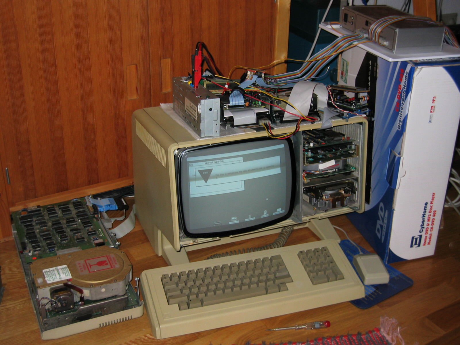
IDEfile as an external device (left image) and as an internal hard disk for the Lisa 2/10 (right image), next to the original 10MB Widget drive.
As shown in the picture on the left, a stand-alone device with a very puristic design can be built using just a LED on the front, like the original ProFile. Apple devices do not have many lamps and switches :-) All connectors and the Volume Select switches are hidden at the
back of the
box.
On the right picture, an IDEfile module is shown that is used as an Widget replacement, next to the real thing. This High End solution with LC disply (not shown here) allows my Lisa 2/10 to run of up to seven different operating systems from one single hard disk! Currently there are only four - LisaOS 2.0/D, LisaOS 3.1 with Office & Workshop, MacOS and SCO Xenix.
Apart from the controls for stand-alone operation, a RS-232 port is provided. It is needed to create the volume structure on the hard disk, and it can be used to control the system. Depending on IDEfile's firmware, diagnostic messages are
written to the serial port, too. To connect it to a PC's COM port, use a 1:1 non-crossover cable.
IDEfile's communication parameters are 19200 baud, 8 bit, no parity.
The ProFile interface
Both ProFile and Widget use the same parallel interface to communicate with their host, the pinout is shown below. External devices are connected through a Sub-D25 connector, internal ones use a 26pin header.

The data bus is 8 bit wide (PD0..7) plus a 9th bit -PPARITY,which generates odd parity. Odd means, if the XOR sum of the data bits is 1, the parity bit will be 0. Besides that, there are six control lines:
- PR/-W signals the direction of data. It is driven by the host, ProFile should enable its output register when PR/-W=1.
- -PSTRB is cycled low by the host whenever data is available from or has been read. ProFile should grab host data during -PSTB=0 or the rising edge, and provide data for the host after the rising edge. The 6522 data sheet calls this "pulse mode, positive edge".
- -PBSY is set low whenever ProFile is busy. This line is connected to the front panel LED, the LED is illuminated whenever ProFile is not busy. Busyness is accepted only during a command handshake phase, not during a data transfer. There is no possibility for the drive to interrupt or slow down transmission, the host sets the pace!
- -PCMD is set low by the host to start a command handshake.
- -PRES is set low by the host to reset the drive.
- PCHK and POCD (Sub-D pin 19) are used by the host to determine whether a drive is connected or not. This lines are grounded inside the drive.
- The strobe pulse width during Apple /// DMA (this is the mode with the most critical timing) is 500ns. Host data is valid 100ns before the falling edge, and a real ProFile changes its output data 200ns after the rising edge.
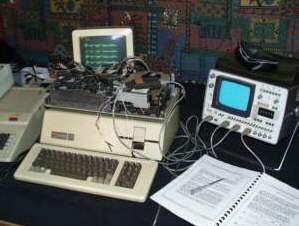
A basic description of the interface protocol could be found in the document "ProFile HD Communications Protocol", edited by David T. Craig and available at lisa.sunder.net. However, this description is not sufficient to allow emulation of the protocol and for this reason a lot of reverse engineering using a logic analyzer had to be done.
 |
 |
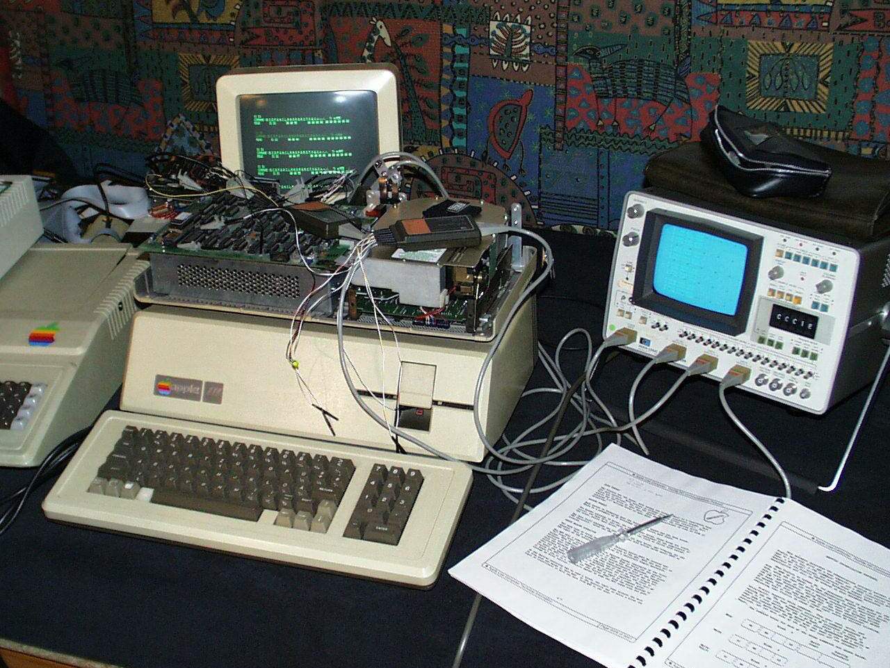
First protocol analysis has been done with a HP1600 Logic state Analyzer (left picture). For detailed timing examination I used a modified PC-LA (NOTA JPL:dead link?) 40MHz logic analyser (the aluminium box on the right).
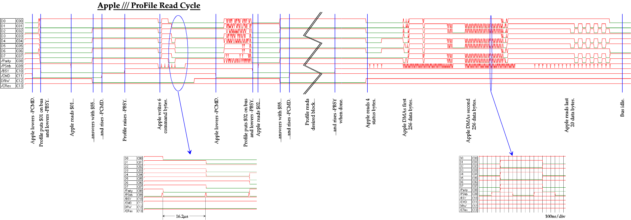
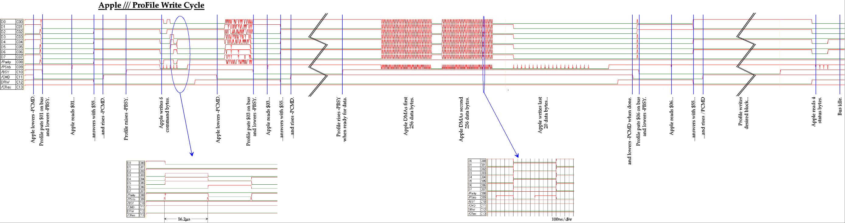
Each read or write access to the drive can be divided into three phases: a command phase, a command confirmation phase, and a data phase. Timing diagrams of an Apple /// reading from and writing to a ProFile are shown below - click on
the image for a full size version.


To start the command phase, the host asserts -PCMD (the '-' indicates an active low signal, active means setting -PCMD=0). If the drive is interested in communication, it answers by putting $01 on the data bus and lowering -PBSY. The host acknowledges that by writing $55 to the bus and de-asserting -PCMD. Every other host response would stop the handshake at this
point. Now the drive rises -PBSY and the host transfers six command bytes into the drive's memory. This is done by writing to the data bus and cycling -PSTB afterwards. Remember that the host sets the pace, it does not wait for the drive to pick up the command bytes. The original ProFile uses a DMA logic to be fast enough, the Z8-03 cpu would be too slow.
At this point the command confirmation phase starts. Again, the host asserts -PCMD and the drive responds with a byte on the bus and an active -PBSY line. The value of this response byte depends on what the drive expects to do next. Valid commands and their responses are listed in Table 1. The host confirms the response byte by putting $55 on the bus and de-asserting -PCMD. Now, the command is executed.
| Command |
byte 0 |
byte 1..3 |
byte 4 |
byte 5 |
response byte |
| Read Block |
00 |
block no. |
retry count |
sparing threshold |
02 |
| Write Block |
01 |
block no. |
don't care |
don't care |
03-06 |
| Write & Verify Block |
02 |
block no. |
retry count |
sparing threshold |
04-06 |
| Format Unit |
03 |
40 8C 44 |
64 |
14 |
05 |
| Scan Unit |
04 |
4D 00 00 |
C8 |
14 |
06 |
| Init Spare Table |
05 |
4D 03 15 |
64 |
14 |
07 |
Table 1: Valid ProFile commands. $03 .. $05 require a Formatter ROM.
A regular ProFile supports only command $00, $01 and $02, for the other commands a special formatter firmware is required. The block number starts with $000000 and goes up to $0025FF for 5MB or $004BFF for 10MB. $FFFFFF indicates the spare table and $FFFFFE the RAM buffer. Retry count and sparing threshold are parameters for the bad block management: the retry count tells the drive how many times to reread a block if a CRC or timeout error occured, and the sparing threshold defines the limit where this block should be considered bad and replaced by a spare. Typical values are $64, $14, that means 100 times and 36%.
For a read access, the drive retrieves the requested block and after about 65ms the data phase starts, where 4 status and 532 data bytes are read by the host. The drive puts the first byte on the bus and de-asserts -PBSY. After reading the byte, the host cycles -PSTB to request the next one. This happens at a rate of up to 1MHz, the host sets the pace and does not wait for the drive. When the host stops reading, ProFile is ready for the next access.
For a write access, after the first command confirmation phase with a response of $03 (write) or $04 (write and verify) the drive de-asserts -PBSY to request the data to be written. Now the host transfers 532 bytes by putting them on the bus and cycling -PSTB. Again, up to 1MHz is possible! When finished, the host asserts -PCMD to initiate a second command confirmation phase. The drive responds with $06 and -PBSY set, which is acknowledged by the host with a $55 and -PCMD inactive. After writing (and verifying if told to do so) the drive puts the first of 4 status bytes on the bus and de-asserts -PBSY. The host reads the status byte, cycling -PSTB to request the next one, and ProFile is ready for a new access.
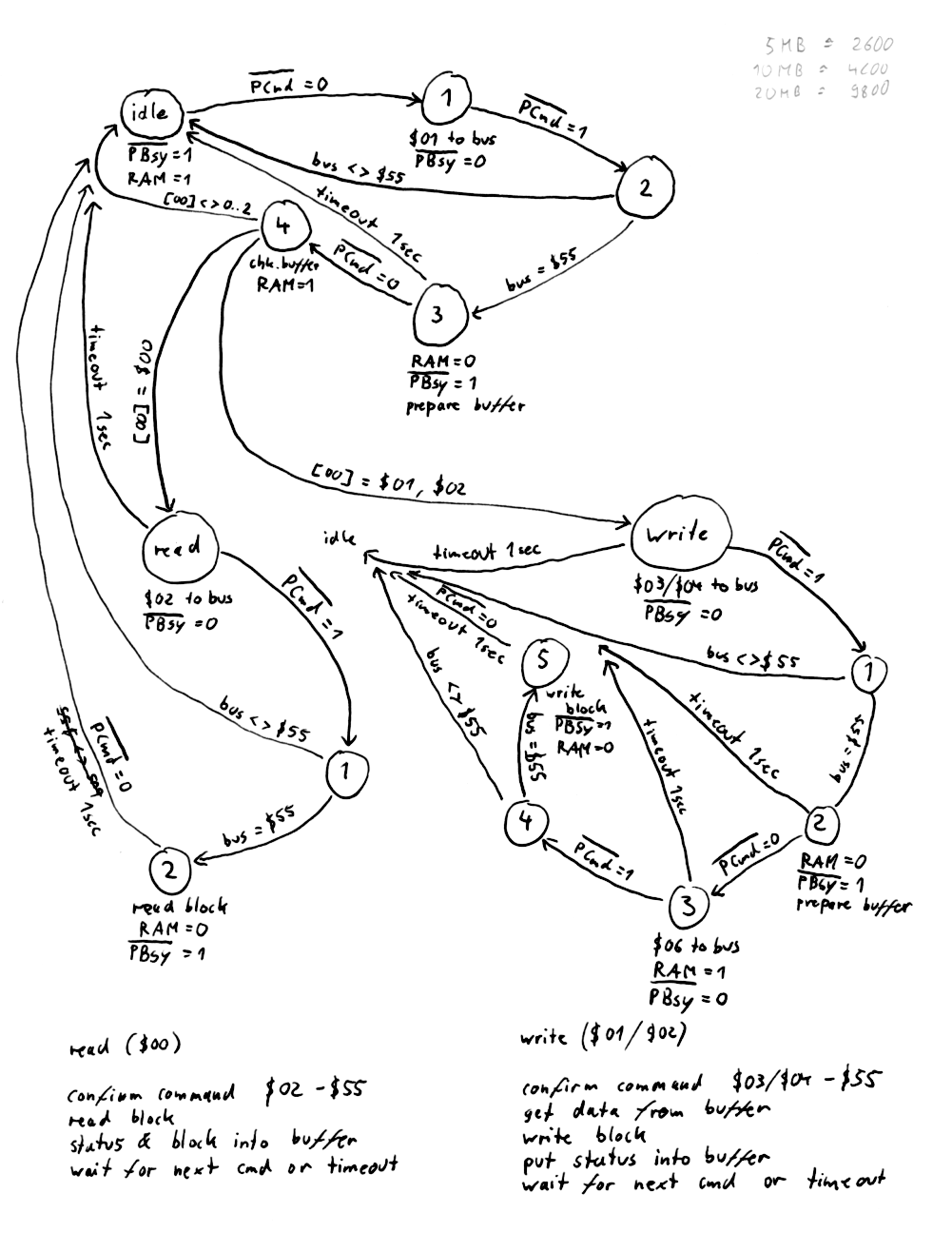
IDEfile's state map, which is derived from this protocol, can be found
here.
Write and Write/Verify are both treated as a simple write operation, because IDE drives do their own verification and bad block management after each write access.
As the result of each read or write access, four status bytes are provided by the drive. The significance of the individual bits is as follows:
| bit |
Status 1 |
Status 2 |
Status 3 |
| 7 |
host acknowledge <> $55 |
Seek Error - cannot read header |
drive has been reset |
| 6 |
>532 bytes sent |
spare table full |
invalid block number |
| 5 |
resend data please! |
- |
- |
| 4 |
Seek Error - cannot read header |
bad block table full |
- |
| 3 |
CRC Error |
cannot read spare table |
- |
| 2 |
Timeout Error |
sparing occured |
- |
| 1 |
- |
Seek Error - wrong track |
- |
| 0 |
operation unsuccessful |
- |
- |
Table 2: Status bytes 1 to 3. Status byte 4 holds the number of errors occured while rereading a block after any read error.
IDEfile uses only bit 7, 4 and 0 of status byte 1 and bit 6 of status byte 3. "Seek Error" is signalled in case of a hard disk failure (IDE ERROR bit set), and "operation unsuccessful" is set if any error occured. I have never observed the "drive has been reset" flag set at a real ProFile, therefore I did not implement it.
IDEfile does not care about the number of bytes read or written. Up to 1024 bytes are supported and the rest is ignored.
As mentioned above, reading block $FFFFFF gets ProFile's spare table. This is the drive's status and configuration block, and it cannot be written by the host. The structure of a spare table is as follows:
- The first 13 bytes show the device name, e.g.
"PROFILE ". Other drives are called "PROFILE 10M " or"WIDGET_10 ".
- The next three bytes hold the device number, which is $000000 for a 5MB ProFile, $000010 for a 10MB ProFile, and $001000 for a Widget 10 drive.
- The next two bytes indicate the firmware revision, e.g. $0398 for
3.98.
- The next three bytes hold the total number of blocks available on the device. This is $002600 for 5MB and $004C00 for 10MB. You see, up to 8GB are possible. IDE reached its first limit at 520MB!
- The next two bytes indicate the number of bytes per block: $0214 means 532. 532 means 512 byted user data and 20 bytes tag. This is the same format Macintosh MFS volumes and 400k/800k disks use. Send a MFS HD20SC with ST225N mechanism a read capacity command - the response will be 532 bytes per sector!
- The next byte contains the total number of spare blocks available on the device, which is $20.
- This is followed by the number of spare blocks currently allocated. A good drive uses less than three spares. When all these 32 blocks are allocated, the host will ask the user to call a qualified Apple Service technician for reformatting.
- The next byte contains the number of bad blocks currently allocated. A bad block turns into a spared block during the next power-on self test.
Finally, the numbers of the spared blocks and the bad blocks are listed (3 bytes per block number), with a $FFFFFF at the end of each list. A spare block is used whenever a read error occured during a read or write/verify command and the number of bad reads during the specified retry count exceeds the threshold value. When all spare blocks are used, the drive will quit its operation. In most cases, this happens due to an un-readable (faded or mis-aligned) address field. Precompensation techniques were not so advanced these days, therefore domain walls move and the magnetic information ages with time. Low-level formatting will cure this problem, because new adress field headers are written to each track. Of course it does not help in the case of mechnical damage (head crash), here a new ST506 or ST412 mechanism is required.
8031 goes DMA
An Apple /// is a rather slow machine, running at 2MHz, but it gets very impatient when it has to deal with ProFile accesses - data is DMAed to and from the drive at an enormous rate of 1MHz! As mentioned above, -PSTB is the only handshake line used for the transfer. There is no way for the ProFile to slow down the host. This means the drive's processor has to wait for -PSTB going low, get one byte of data from its RAM buffer, wait for -PSTB going high, and put it on the PD bus within 1 microsecond. And beside that, it has to do some housekeeping, incrementing counters, do range checking, and so on. This would require a very fast microcontroller, something like a Dallas DS80C420 running at 40MHz, and even in this case many latency and timing problems would have to be mastered! After many calculations and experiments I decided to go the same way as Apple did some 20 years ago: keeping the processor speed low and do all timing-critical transfers with a DMA logic. This makes the hardware more complex (and more challenging to design :-), but it simplified software development and improved the overall reliability of the system significantly.
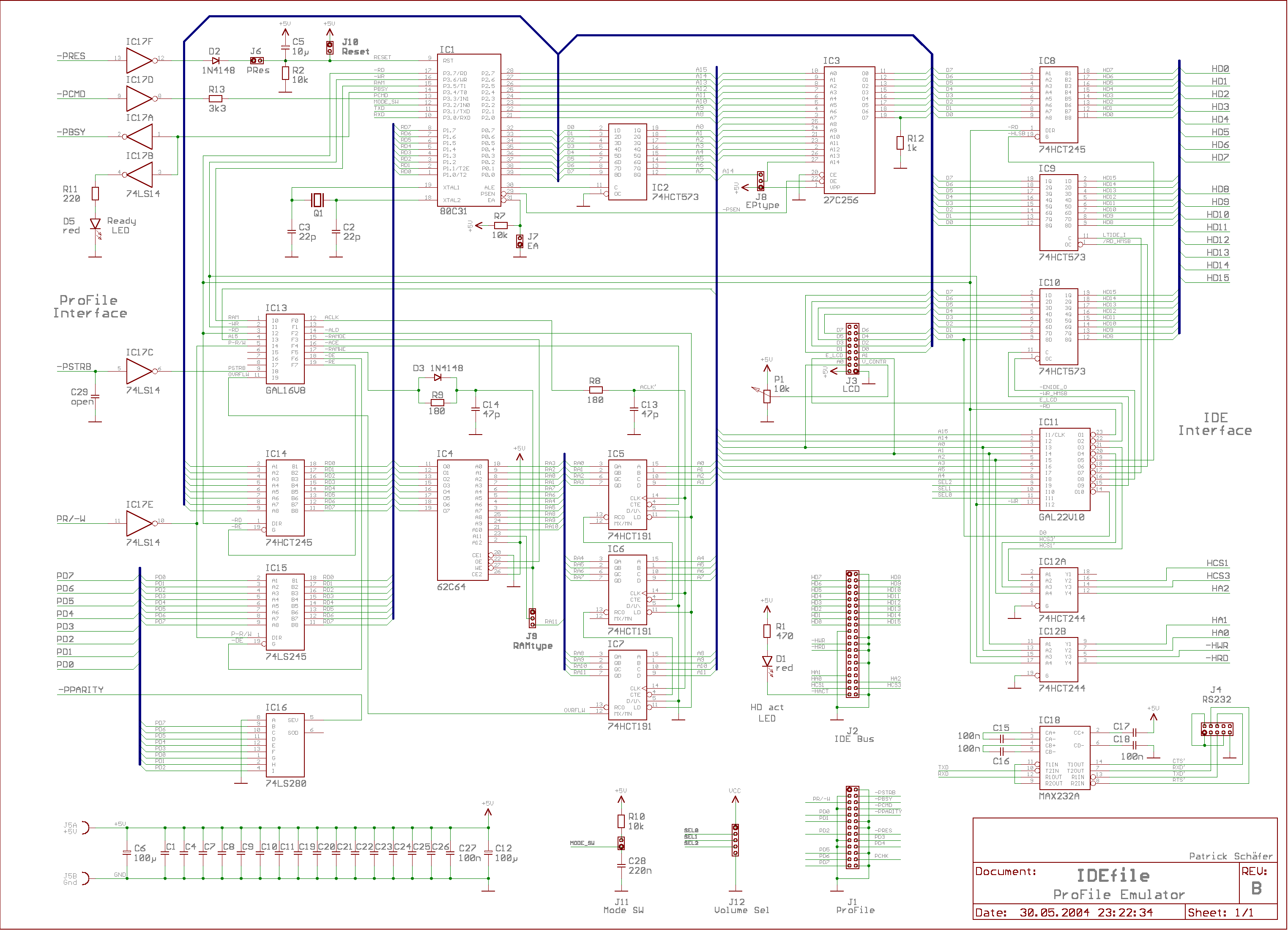
Shown below is a schematic diagram of the IDEfile board. Click on the image for a full-sized version.
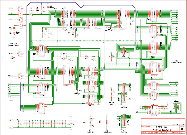
The circuit can be divided into three main parts: controller, IDE interface, and host interface with DMA logic. IC1 to IC4 form the controller part. IC1 is an 80C31 microcontroller equipped with external progam memory (IC3) and data RAM (IC4). It is operated at 18.452MHz. For compatibility with 'old' processors rated up to 12MHz only, an 11.059MHz crystal together with a modified software could be used instead. Jumper J7 allows the use of controllers with internal flash ROM (e.g. AT89C52), J8 has to be set according to the EPROM type, and J9 to the SRAM type used. After power-on, a reset signal is generated by the R/C combination R2/C5. If J6 is closed, RESET will be connected to the inverted -PRES line and IDEfile restarts each time the Lisa reboots. The functions of these jumpers are summarized in Table 3.
| Jumper |
open / upper position |
closed / lower position |
| J6: RESET generation |
only at power-up |
at power-up and from -PRES |
| J7: ROM select (EA) |
internal flash ROM (IC1) |
external EPROM (IC3) |
| J8: ROM select |
27C64 (8kB) or 27C128 (16k) |
27C256 (32kB) |
| J9: RAM select |
6264 (8kB, only 4kB used) |
6116 (2kB) |
Table 3: Jumper settings for reset generation, RAM and EPROM type. J8 can also be used to run two software versions from a single 27C256. The upper position selects the upper 16kB of the EPROM (A14=1), the lower position selects the lower 16kB (A14=0).
All peripheral functions are controlled by two logic arrays: IC11 and IC13. IC11, a GAL22V10, serves as an address decoder and generates the chip select signals for the IDE interface (J2) and the display module (J3). Besides that, it contains the latch for the volume select signals SEL0..2. These signals are generated by three DIP switches connected to J12 which represent the number of the desired volume. All timing signals are generated by IC13, a GAL16V8.
For setup and diagnostics, a serial interface is implemented with a MAX232A level shifter (IC18). The 'A' type requires only four 100nF capacitors. A regular MAX232 could be used instead, but in this case C15-C18 have to be chosen according to the manufacturer's datasheet. J4 can be connected directly to a PC's RS-232 COM port, its pinout is given below.

IC8 to IC12 make up the IDE interface. Usually, IDE is memory-mapped into an 8086's address space, therefore it is a 16 bit bus. To connect it to an 8 bit microcontroller, the upper data byte (MSB) has to be latched. This is the task of IC9 and IC10, two 74HCT573 8 bit latches. For a write access, the controller first stores the MSB into IC10. Then, the LSB is written to the host interface and all required control signals are generated, so that the hard disk could pick up 16 data bits at the same time. Analogous to this, during a read access the MSB is latched into IC9 while the LSB is read directly. In a second step, the controller fetches the MSB from the latch. The LSB data lines and control signals are buffered by IC8 respectively IC12. D1, a red LED on the PCB, signals disk drive activity.
The data buffer RAM IC4 has been mentioned before as a part of the controller circuit, but it is not connected directly to the microcontroller. Its address and data lines are isolated by IC5 to IC7 and IC14. IC5..7 are 74HCT191 4 bit binary counters with preset inputs. As long as their -LD input is low, the value from the preset inputs A..D appears at the outputs QA..QD. After -LD is made high, this value is latched and incremented with each falling edge at the CLK input. Now the 80C31 address lines are connected to the preset inputs and the counter outputs act as address signals for the RAM chip. This allows the controller to access the RAM directly (while -LD=0) and to let -PSTRB pulses increment the data buffer address starting from the last latched value (while -LD=1). For DMA operation, IC4 is disconnected from the data bus by turning off IC14.
The host can read the RAM output at any time through IC15, but write accesses are only permitted at certain times by the timing GAL IC13. This means IC15 is always enabled when PR/-W=1, but for PR/-W=0 it is only active when -PSTRB=0 and DMA mode selected. To let the microcontroller communicate directly with the host during the handshake phases, the buffered host bus is connected to port P1. A 74LS280 parity generator, IC16, generates the odd parity required by the host interface.
The state of the -PBSY signal issued by the microcontroller is displayed by LED D5. It works as a combined power lamp and machine status indicator, as the original ProFile lamp did. The LED is lit whenever IDEfile is not busy.
Table 4 lists all connectors and controls of the IDEfile board.
| Jumper |
Function |
| J1 |
Host interface. Connect to a Sub-D25 female, and then to your Apple /// or Lisa. |
| J2 |
IDE interface. Connect to an IDE drive set as primary ("master").
|
| J3 |
LCD module. Connect to a HD44780-compatible liquid crystal display. Pins 15+16 are unused and may be used for backlight supply according to the display manufacturer's datasheet. |
| J4 |
RS232 interface. Connect to a Sub-D9 female, and then to your PC's COM port. |
| J5 |
+5V supply. Depending on the amount of CMOS parts used, IDEfile consumes between 400 and 600mA. |
| J6..J9 |
System configuration. See Table 3 for details. |
| J10 |
Reset button. Press to reset the system. |
| J11 |
Mode button. Press to select the next volume immediately. |
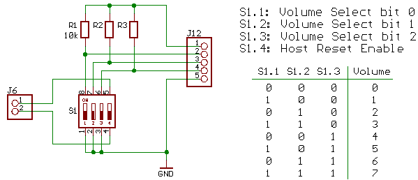
| J12 |
Volume Select switches 0..2. A low level means 1, a high level 0. These switches are read only after a reset. |
| D5 |
Ready LED. This is the power/ready light for the front panel. |
| P1 |
LC display contrast potentiometer. |
Table 4: Jumpers and connectors and their functions.
Shown below is an example how to wire the volume selector. The fourth DIP switch in the block is used to enable the host reset, i.e. close jumper J6. In the truth table, 1 means closed and 0 means open.
Want to build your own?
At first, a warning: This is not a beginner's project! If you want to get this thing running, you should have some experience building digital circuits. Though the software performs excessive self-tests and is able to
discover many failure modes, you should have an oscilloscope available for troubleshooting. With manually etched PCBs, it is necessary to solder the components to both sides of the board. This requires some talent to solder 'around the corner' and a good component placement strategy.
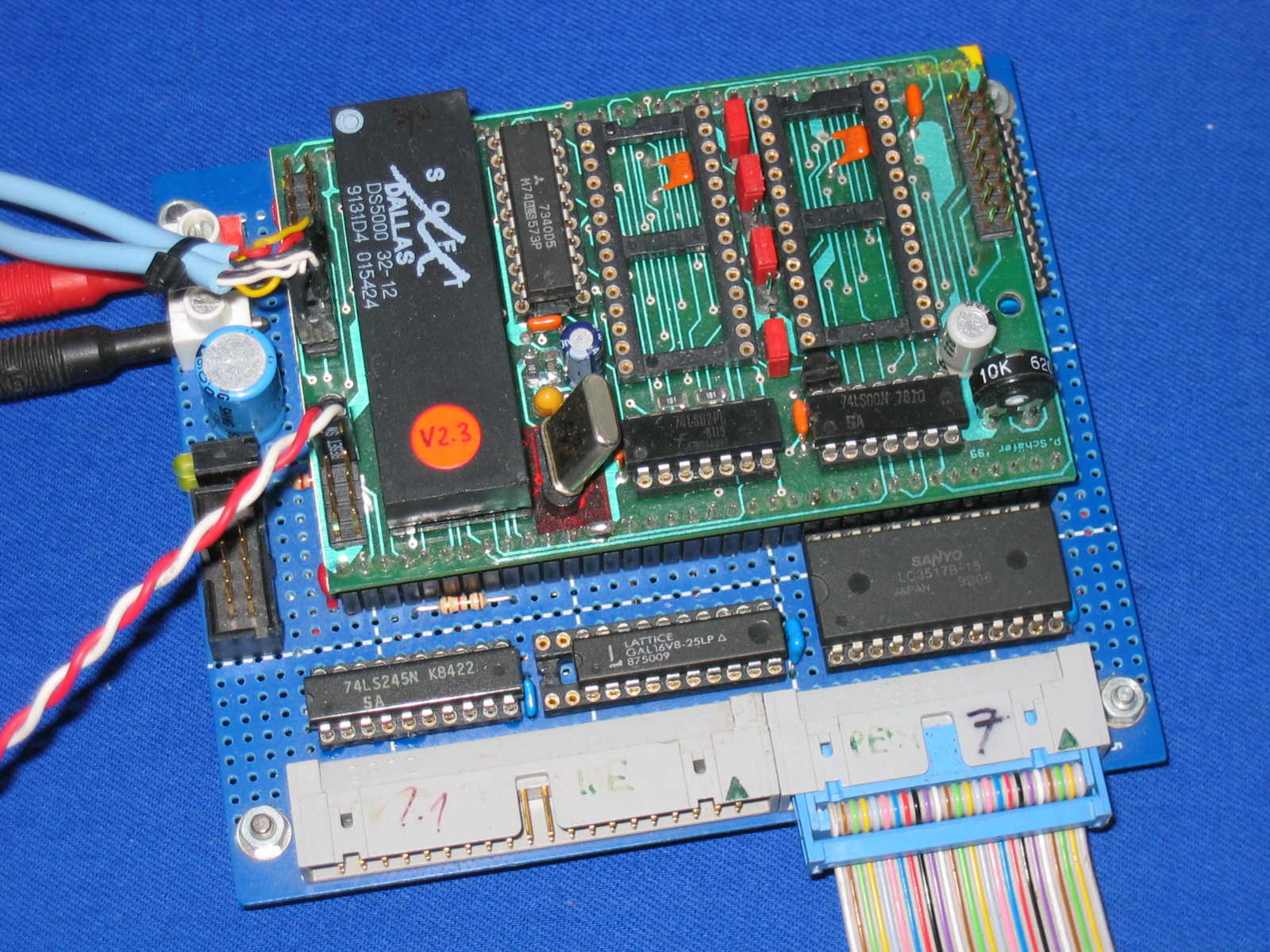
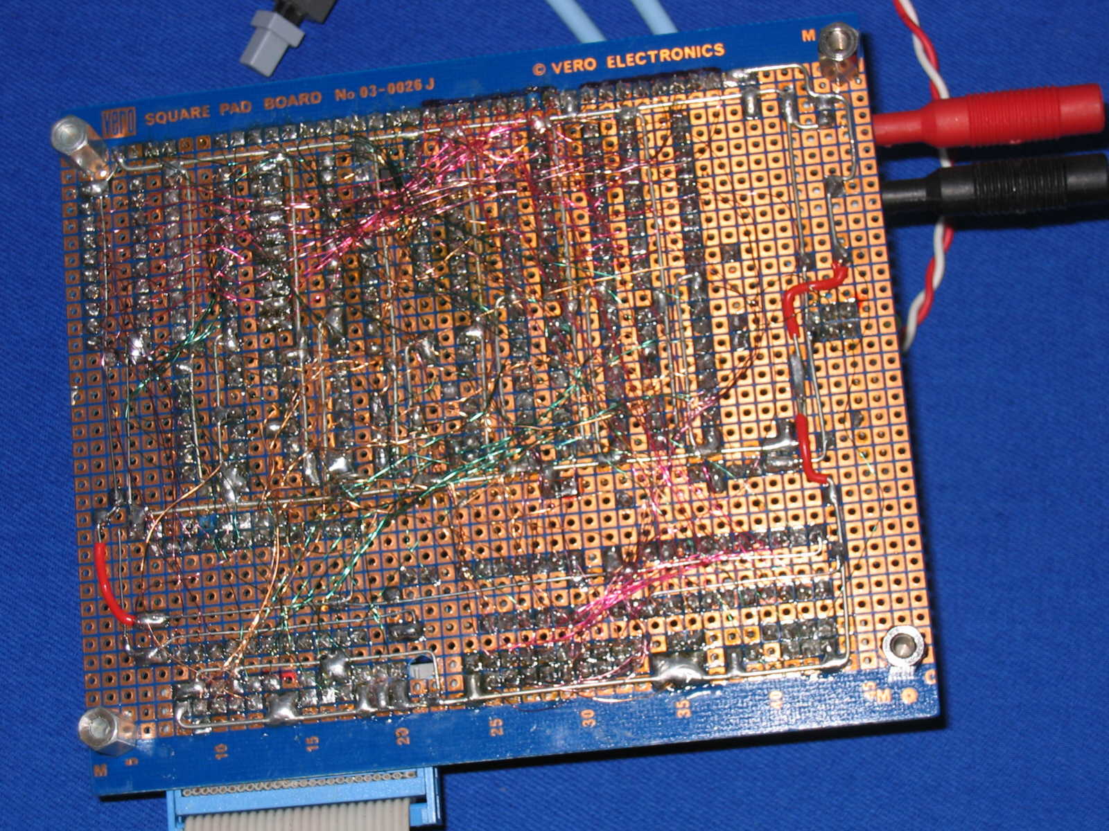
Up to now, half a dozen IDEfile systems have been build. The first prototype was wrapped on a Vero board and looked like this (front
/ back).
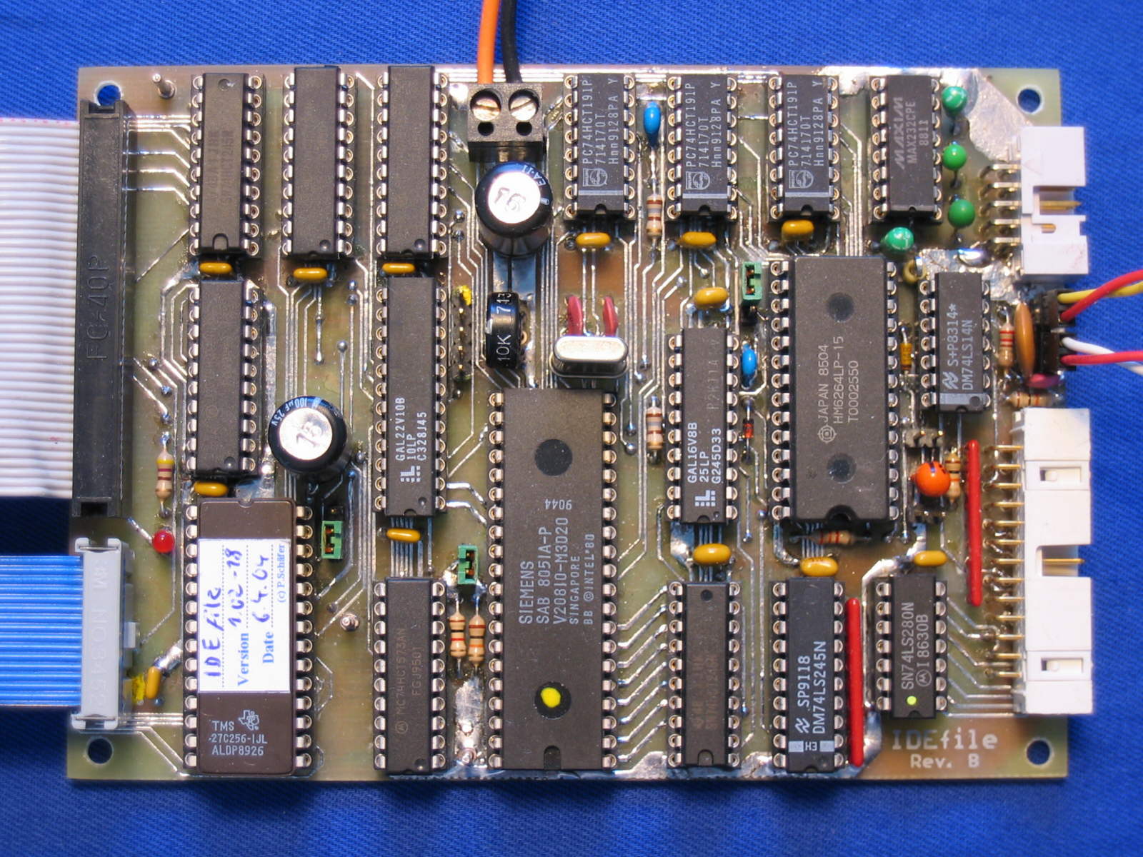
Most of the components are located below the processor module and therefore not visible on the photo. For the second generation I designed a PCB. Professionally made, it looks like this. For
those of you, who want to etch their own board, here are the necessary files available for download:
One of the following firmware files is required for operation. Two versions are available, one for an 18.452MHz crystal and one for 11.059MHz. They differ only in the values for the timing constants, i.e. IDEfile will run with the wrong file, but the serial interface won't work and some timing parameters would be off spec. Each software version is avalilable as a 'debug version', too. Debug versions are somewhat more talkative, each host access will be reported to the serial interface. This can be very helpful during software installation or troubleshooting, but it slows down the system significantly. 16 characters at
19k2 take around 10ms to transmit, increasing the access time for a block by a factor of three. All these versions are derived from the same source code using conditional assembly. The code was generated using Alfred's AS(NOTA JPL:dead link?) assembler.
All binary files have a size of 8kB and fit into a 27C64 EPROM or the flash memory of an AT89C52. It is possible to burn two firmware files into a 27C256 and mis-use J8 to select the upper or lower 16kB of this 32kB chip.
Please contact me directly for programmed GALs and in the case you are interested in a professionally made PCB. And please don't ask me for the source code or the GAL equations :-)
- logo.gif:
This is the IDEfile logo for your front panel.
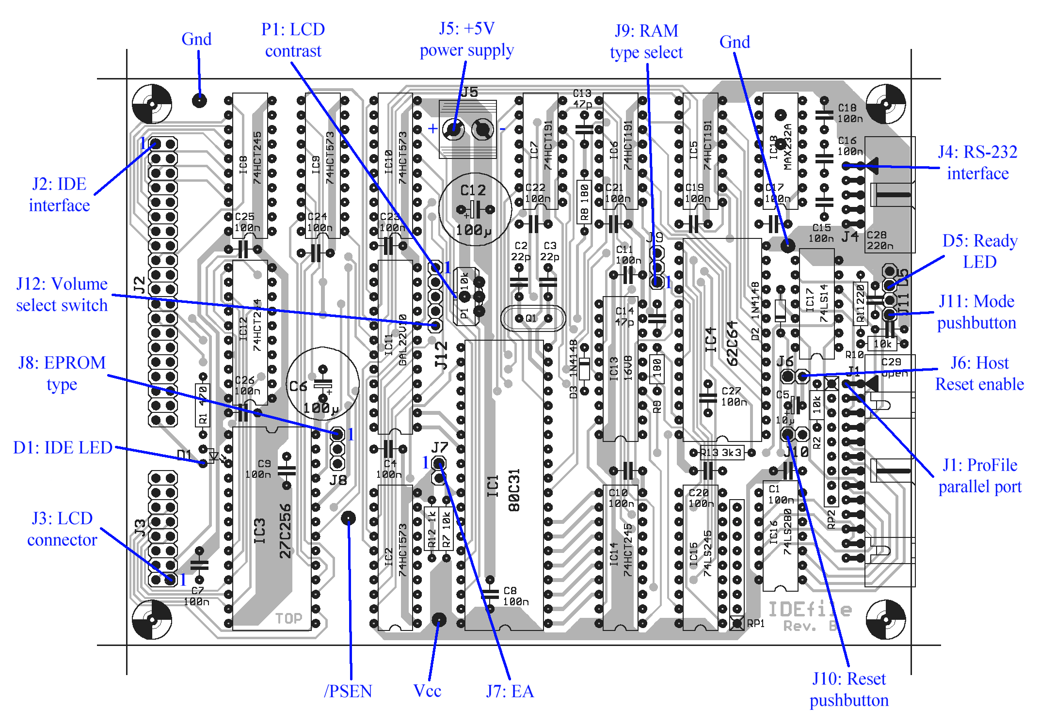
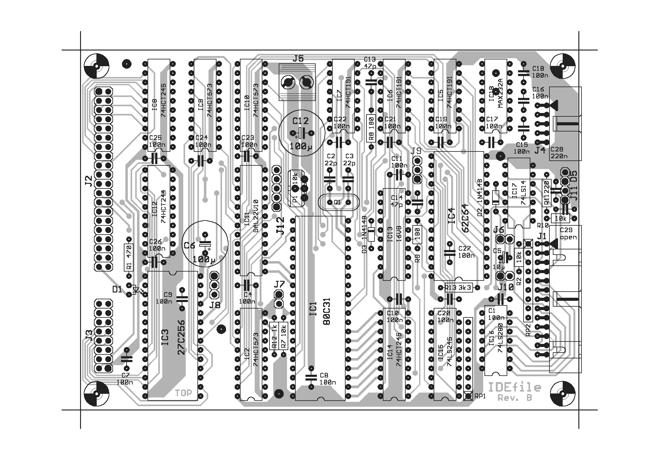
After obtaining a PCB and the required components, assemble the whole thing. Don't forget to use sockets for the ICs, at least for the EPROM, the GALs and the controller. The result should look similar to the photo below. Click on the images or full-sized pictures. The location of the jumpers and connectors can be taken from the placeplan below, their function is
explained in Table 3 and 4.
 |
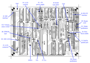 |
A photo of the assembled PCB (left) and the position of the jumpers and connectors (right).
With empty IC sockets, the board should not consume any significant power. With pin 39 of J2 grounded, the red LED D1 should illuminate. Immediately after power-on, a short reset pulse should be generated at pin 9 of IC1. Now plug in IC17, IC18 and use a short wire to connect pin 10 and 11 of IC1. This crosses the RxD and TxD lines. Hook up the board to your PC or Mac and start your terminal program. You should see anything you type echoed back, in half duplex mode TTWWOO TTIIMMEESS. Connect a LED to the D5 connector, it should illuminate when pin 14 of IC1 is grounded.
Okay? Now the next step: plug in IC1, IC2, IC17 and the EPROM IC3. Set the jumpers J6..9 as required for your chips. Default setting is J6 closed, J7 closed, J8 upper position, J9 upper position. Apply power and get a message like
 IDEfile -- ProFile Emulator V1.02D
   (c) Patrick Schaefer, 2004

 No RAM found! System halted.
 _
together with a flashing LED. Short J10 (or press the reset button connected to J10) and the show repeats. Now plug in IC4..7 and 13..16. These are the parts for RAM/DMA and for the host interface. Apply power and read
 IDEfile -- ProFile Emulator V1.02D
   (c) Patrick Schaefer, 2004

 0FFF bytes RAM found. RAM test passed.
 Waiting for HD...
   HD Timeout!

 >_
Timeout occurs if the hard disk does not respond within 15 seconds. Press 't' and <cr> to enter test mode. At the asterisk prompt, use the commands described below in the RS232 commands section to check the host interface. Using the 'e' and 'd' command in main mode you should be able to write to and read from the RAM, unless you
activated DMA with a 'r 00' command in the test mode.
As the last step, populate the missing ICs and connect a hard disk. If the disk is recognized by IDEfile, continue with the next chapter. If not, try to give it a few seconds lead before applying power to the board, or hold the reset button until the disk has spun up. Some older HDs hang if they are accessed too early. In the current software version, a 500ms delay after startup is implemented (plus the time for the RAM test) before the drive is accessed, which is sufficient for most drives, but there might be some exceptions.
Troubleshooting
IDEfile performs a self test after power-on. RAM, hard disk and a part of the logic are checked before the system calls itself ready. In case of a fatal hardware failure, the controller will flash D5, write an error code to Port P1 and try to write text messages to serial port and display. The codes are listed in Table 5.
| P1 code |
Test step failed |
| $10 |
PCmd (P3.3) stuck high |
| $11 |
Port 1 / XData bus did not read 55h |
| $12 |
Port 1 / XData bus did not read AAh |
| $20 |
no RAM found (check J9!) |
| $30..3F |
RAM page $0..$F failed RAM test |
| $77 |
spurious timeout interrupt occured |
| $FF |
regular operation, waiting for host command |
Table 5: Power-on self test error codes.
Hard disk errors are reported in the form "HD failed (xx)" where xx is the error code returned from the IDE error status register. "Check Config" on the display just means that the volume table on the hard disk is invalid. Use the procedure described below to set up your system.
Setting up the system
Connect the IDEfile PCB to your IDE drive and apply power to both devices. The hard drive should be configured as a primary (aka "master") device. Hook up IDEfile's RS-232 connector to your computer's serial port and run your favourite terminal program. After power-up, you should see something like this:
 IDEfile -- ProFile Emulator V1.02
   (c) Patrick Schaefer, 2004

 07FF bytes RAM found. RAM test passed.
 Waiting for HD... Ready.

 No volumes defined.
 >_
Now you need to define at least one volume. From Lisa's point of view, each volume is a different hard disk drive. Up to eight are possible, and only one can be used at the same time. Press 'i' and <cr> to enter Hard Disk Install. IDEfile reports the name and size of your hard disk and asks for the type of the first volume:
 Hard Disk Type Maxtor 7120 AT
 1024 cylinders, 0014 heads, 0017 sectors.
 Total capacity: 00121599 kBytes.

 Volume types:   0 -> ProFile 5MB (2600h)     2 -> Widget  10MB (4C00h)
                 1 -> ProFile 10MB (4C00h)    3 -> Widget  20MB (9800h)

 Enter type for Volume 0 (0..3):_
Capacity and cylinder count will roll over for huge drives, but as these drives are accessed in LBA mode this should be only a cosmetic problem. However, do you really want to use a 100GB drive with your Lisa??
Now enter the a number between 0 and 3 for the desired volume type. IDEfile will calculate the remaining space on disk and ask for the next volume type, until eight volumes are defined or the disk is full. Press 'y' to write the volume table to disk or any other key to exit. IDEfile is now ready for use.
Creating a new volume structure does not change the data blocks on the disk, that means some kind of reconfiguration without losing all data is possible. For example overwriting a volume type configuration of 1-1-0-3 with 1-1-0-1-2 will leave the first three volumes intact, but make the 4th volume (former type 3, now one type 1 plus one type 2) useless. Nevertheless, always do a backup of your data before changing anything at the hard disk structure!
Using IDEfile
After creating a volume table, IDEfile is ready for use. Connect it to your Apple II, Apple /// or Lisa and install your favourite operating system. From the host's point of view, IDEfile behaves exactly like an original ProFile or Widget and can be used with any software designed for these drives. Read this
file to learn what does not work with the current software version.
Each volume represents an independent hard disk. Depending on the user interface chosen, there are different ways to select the active volume:
- System without LCD: set the DIP switches to the desired volume number. On means 1 and Off means 0, i. e. Sw0 Off, Sw1 Off, Sw2 Off selects Volume 0, Sw0 off, Sw1 on, Sw2 on selects Volume 6. The selected volume will be active after power-on, after the reset button has been pressed, and after a ProFile reset has been issued by the host. Lisa resets the hard disk drives during its kernel selftest.
- System with LCD: press the mode pushbutton until the desired volume number is displayed. This changes the volume immediately, so be careful what you do!
- In both cases, it is possible to change the volume through a RS-232 command. Enter 'v 0x' to immediately select volume x. If x is not available, the next defined volume (in most cases Volume 0) will be chosen. Enter 'v' without any parameter to display the current volume number. Enter 's' to display the current volume configuration.
!!! NEVER change the volume while the drive is mounted !!! LisaOS keeps most of the file allocation data in memory and changes are written back to the disk only very occasionally. If you switch to another volume, Lisa will write the old MDDF to the new volume, zapping all the data. So always unmount the drive or shut down the system before changing anything! For the same reason, you must not turn off any external drive until the Lisa tells you to do so.
It is safe to change the volume setting when you are in Lisa's boot menu, but not in the Environments Window. The easiest way is to set the DIP switches to the new volume number and reboot the machine. Lisa issues a Reset pulse to all drives during the power-on kernel tests, and this will also reset IDEfile, selecting the new volume.
Below are some photos of my Lisa 2/10 in action. Click on the image for full size.
 |
 |
 |
| The Environments Window, ... |
... LisaOS 3.1 booting, ... |
... and running! |
RS-232 commands
IDEfile understands the following commands. In all cases, xx or xxxx means a two- or four-digit hex number. If the number is shorter, add leading zeros.
- c - Dump command buffer. Displays the last command received from the host.
- d - Dump data buffer. Displays the contents of the data buffer. After a host read or write command, the last four bytes of the first line hold the status bytes and the block data starts from the second line. Usually, one block has 532 ($214) bytes. After a manual read or write operation, the 1024 data bytes (two IDE sectors) start from the first line.
- e xxxx,yy or e yy - Enter hex data. Change buffer adress xxxx to yy. To change consecutive bytes, only the value needs to be entered.
- h or ? - Show Help text. Displays a command list.
- i - Hard Disk Install. Used to setup the volume table, as described above. Nothing is changed on the disk unless the write operation is confirmed by pressing 'y'.
- r xxxx - Read block into buffer. Reads block xxxx from the selected volume into the data buffer. This can be used to examine the data on the disk. There is no range check, i. e. reading block 2600 of a 5MB ProFile will give you the first block of the following volume.
- s - Show volume configuration: Displays the volume table, or an error message if no volumes are defined.
- t - Test hardware interface: This was used during development and may help troubleshooting your system.
- b xx - Set PBusy (P3.4) to low (00) / high (01). D5 will be lit and -PBSY will be high when PBusy is low.
- c xx - Set PCmd (P3.3) to low (00) / high (01). The default value is high so that -PCMD can act as an input. Setting PCmd low inhibits any host access.
- i - Read ProFile data bus PD (P1).
- o xx - Write xx into ProFile data bus PD (P1). Write $FF into P1 before trying to read the PD lines.
- r xx - Connect RAM to bus (00) / CPU (01).
- s - Show Volume Switch and ProFile handshake line status.
- any other key - return to main menu
- v xx - Select volume: Enter 'v 0x' to select volume x. If x is not available, the next defined volume (in most cases Volume 0) will be chosen. Entering 'v' without any parameter displays the current volume number.
- w xxxx - Write buffer into block: Writes data buffer into block xxxx of the selected volume. There is no range check, i. e. writing block 2600 of a 5MB ProFile will write the first block of the following volume.
Benchmarks
Apple's ProFile Certify Program was chosen to determine the speed of IDEfile's emulation. This Apple /// program writes $260 blocks to the drive and reads them back afterwards.
| Drive |
FW1.00, 11MHz, Debug + LCD |
FW1.00, 11MHz, LCD |
FW1.00, 18MHz, Debug + LCD |
FW1.00, 18MHz, LCD |
| Original ProFile 5MB |
1:10 |
| Maxtor 7120AT (CHS) |
3:55 |
1:30 |
3:40 |
1:10 |
| Maxtor 7040AI (CHS) |
|
|
3:40 |
1:10 |
| Toshiba MK1403MAV (1GB, LBA) |
|
|
2:35 |
0:40 |
Table 3: Transfer time in minutes for writing and reading 260h blocks
As expected, IDEfile runs faster with modern hard disks. However, only using an old 1990 drive will result in authenthic system performance :-).
| Drive |
Boot Time |
| IDEfile 1.02 18MHz/Debug with LCD |
1:23 |
| IDEfile 1.02 18MHz with LCD |
1:09 |
| IDEfile 1.02 18MHz without LCD |
1:08 |
| Orignal ProFile 5MB |
1:13 |
| Original Widget_10 |
2:10 |
Table 4: Time to boot LisaOS3.1 (in minutes)
The debug firmware reports each host access through the R-S232 port. This slows down the system significantly, therefore it should only be used for debugging purposes.
Disclaimer & Copyright
This web page has been created by
Dr. Patrick Sch�fer
An der Gr�ngesweide 1
D-65760 Eschborn
Germany
PSchaefer@lycosxxl.de
As I cannot take any responsibility for anything outside my reach, I explicitly disassociate myself from the contents of any page linked here.
The program and circuitry given here are free for personal use, but are not in the public domain. Freeware in contrast to public domain means that while the author makes the product available for free, the copyright is still hold by the author. This does mean that you can build the circuit and use the software without paying any fees, but you may not sell or redistribute the software or the circuit design, neither unmodified nor versions derived from it, without prior written permission from the author.
I will give absolutely no guarantee that the software or circuit will work as described, that it will not destroy your computer, the circuit itself, or any peripherials connected to it. I also refuse any responsibilty for data losses resulting from the use of this software and circuit design. It's freeware. If you want some guarantee, buy a commerial product. It is explicitly prohibited to use the software and circuit described here in places where failure or malfunction may be dangerous to the health or result in monetary losses.
IDEfile is copyright (c) by Dr. Patrick Sch�fer, 2004
Apple, Lisa, ProFile, Widget and the ProFile communications protocol are (c) by Apple Computer Inc.
This page is hosted at John, a server of the Computer Club der RWTH Aachen e.V.
