


This sections describes the formats of the files used by
the emulator.
ROMS.BIN:
| 00000-03fff | Ordinary Spectrum rom |
| 04000-05fff | Interface I rom (8K) |
| 06000-09fff | First SamRam rom (contains BASIC) |
| 0a000-0dfff | Second SamRam rom (contains monitor,...) |
| 0e000-11fff | First Spectrum 128K rom (active at RESET) |
| 12000-15fff | Second Spectrum 128K rom (contains BASIC) |
The ordinary rom has not been modified. The Interface I rom has
undergone some modifications, to speed up the RS232 input/output
routines. If you don't like this, or want to use another version of the
Interface I, you could put that code at the right place in the ROMS.BIN
file. The interface I should work properly, although the RS232 will be
slower (always FORMAT the "b" or "t" channel at 19200 baud, by the way,
if you replace the rom code, there's no point in waiting for nothing!)
The microdrive routines have not been modified in any way. Here are the
changes of the Interface I rom:
| Address | Old | New | Address | Old | New |
| 0B9E | ED | ED | 0D20 | FB | 00 |
| 0B9F | 5B | FC | 0D2A | 37 | ED |
| 0BA0 | C3 | F5 | 0D2B | F3 | FD |
| 0BA1 | 5C | C3 | 0D2C | CE | 18 |
| 0BA2 | 21 | 34 | 0D2D | 00 | 10 |
| 0BA3 | 20 | 0C | 0D4C | FB | 00 |
These changes are not likely to cause problems; there are several versions of the Interface I rom around, and program developers know this. It is also a bit pointless to check whether the Interface I rom hasn't been modified; who would put his snapshot software in there anyway, and that's what those people are afraid of.
The first and second SamRam rom have been modified more extensively. The
biggest problem was that switching the upper 32K ram bank is very fast
in reality, but on the PC two blocks of 32K bytes had to be REP
MOVSWded. But since no programs know of the SamRam code anyway, this
won't cause any more problems it wouldn't already cause either.
The two Spectrum 128 roms have not been modified.
.TAP FILES:
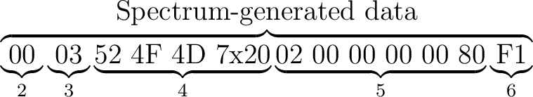
The .TAP files contain blocks of tape-saved data. All blocks start with
two bytes specifying how many bytes will follow (not counting the two
length bytes). Then raw tape data follows, including the flag and
checksum bytes. The checksum is the bitwise XOR of all bytes including
the flag byte. For example, when you execute the line
SAVE "ROM" CODE 0,2 this will result:
| 1: | First block is 19 bytes (17 bytes+flag+checksum) |
| 2: | flag byte (A reg, 00 for headers, FF for datablocks) |
| 3: | first byte of header, indicating a code block |
| 4: | filename |
| 5: | header info |
| 6: | checksum of header |
| 7: | length of second block |
| 8: | flag byte |
| 9: | first two bytes of rom |
| 10: | checksum (`checkbittoggle' would be better) |
The emulator will always start reading bytes at the beginning of a block. If less bytes are loaded than are available, the other bytes are skipped, and the last byte loaded is used as checksum. If more bytes are asked for than exist in the block, the loading routine will terminate with the usual tape-loading-error flags set, leaving the error handling to the calling Z80 program.
Note that it is possible to join .TAP files by simply stringing them
together, for example:
COPY /B FILE1.TAP + FILE2.TAP ALL.TAP
For completeness, I'll include the structure of a tape header. A header
always consists of 17 bytes:
| Byte | Length | Description |
| 0 | 1 | Type (0,1,2 or 3) |
| 1 | 10 | Filename (padded with blanks) |
| 11 | 2 | Length of data block |
| 13 | 2 | Parameter 1 |
| 15 | 2 | Parameter 2 |
The type is 0,1,2 or 3 for a Program, Number array, Character array or
Code file. A screen$ file is regarded as a Code file with start address
16384 and length 6912 decimal. If the file is a Program file, parameter
1 holds the autostart line number (or a number > =32768 if no LINE
parameter was given) and parameter 2 holds the start of the variable
area relative to the start of the program. If it's a Code file,
parameter 1 holds the start of the code block when saved, and parameter
2 holds 32768. For data files finally, the byte at position 14 decimal
holds the variable name.
.MDR FILES:
The emulator uses a cartridge file format identical to the `Microdrive File' format of Carlo Delhez' Spectrum emulator Spectator for the QL. The following information is adapted from Carlo's documentation. It can also be found in the `Spectrum Microdrive Book', by Ian Logan (co-writer of the excellent `Complete Spectrum ROM Disassembly').
A cartridge file contains 254 `sectors' of 543 bytes each, and a final
byte flag which is non-zero is the cartridge is write protected, so the
total length is 137923 bytes. On the cartridge tape, after a GAP of
some time the Interface I writes 10 zeros and 2 FF bytes (the preamble),
and then a fifteen byte header-block-with-checksum. After another GAP,
it writes a preamble again, with a 15-byte record-
descriptor-with-checksum (which has a structure very much like the
header block), immediately followed by the data block of 512 bytes, and
a final checksum of those 512 bytes. The preamble is used by the
Interface I hardware to synchronise, and is not explicitly used by the
software. The preamble is not saved to the microdrive file:
| offset | length | name | contents |
| 0 | 1 | HDFLAG | Value 1, to indicate header block |
| 1 | 1 | HDNUMB | sector number (values 254 down to 1) |
| 2 | 2 | not used | |
| 4 | 10 | HDNAME | microdrive cartridge name (blank padded) |
| 14 | 1 | HDCHK | header checksum (of first 14 bytes) |
| 15 | 1 | RECFLG | - bit 0: always 0 to indicate record block |
| - bit 1: set for the EOF block | |||
| - bit 2: reset for a PRINT file | |||
| - bits 3-7: not used (value 0) | |||
| 16 | 1 | RECNUM | data block sequence number (value starts at 0) |
| 17 | 2 | RECLEN | data block length (< =512, LSB first) |
| 19 | 10 | RECNAM | filename (blank padded) |
| 29 | 1 | DESCHK | record descriptor checksum (of previous 14 bytes) |
| 30 | 512 | data block | |
| 542 | 1 | DCHK | data block checksum (of all 512 bytes of data |
| block, even when not all bytes are used) |
repeated 254 times
(Actually, this information is `transparent' to the emulator. All it does is store 2 times 254 blocks in the .MDR file as it is OUTed, alternatingly of length 15 and 528 bytes. The emulator does check checksums, see below; the other fields are dealt with by the emulated Interface I software.)
A used record block is either an EOF block (bit 1 of RECFLG is 1) or contains 512 bytes of data (RECLEN=512, i.e. bit 1 of MSB is 1). An empty record block has a zero in bit 1 of RECFLG and also RECLEN=0. An unusable block (as determined by the FORMAT command) is an EOF block with RECLEN=0.
The three checksums are calculated by adding all the bytes together modulo 255; this will never produce a checksum of 255. Possibly, this is the value that is read by the Interface I if there's no or bad data on the tape.
In normal operation, all first-fifteen-byte blocks of each header or
record block will have the right checksum. If the checksum is not
right, the block will be treated as a GAP. For instance, if you type
OUT 239,0 on a normal Spectrum with interface I, the microdrive motor
starts running and the cartridge will be erased completely in 7 seconds.
CAT 1 will respond with `microdrive not ready'. Try it on the
emulator...
.SCR FILES:
.SCR files are memory dumps of the first 6912 bytes of the Spectrum memory. A coordinate (x,y), x between 0 and 255 and y between 0 and 192, (0,0) being the upper left corner of the screen, corresponds to the pixel address
| 16384+INT (x/8)+1792*INT (y/64)-2016*INT (y/8)+256*y |
The lowest three bits of x determine which bit of this address corresponds to the pixel (x,y). This bit-map constitutes the larger part of the screen memory, 256*192/8=6144 bytes. The final 768 bytes are attribute bytes. The address of the attribute byte corresponding to pixel (x,y) is
| 22528+INT (x/8)+32*INT (y/8) |
.Z80 FILES:
The old .Z80 snapshot format (for version 1.45 and below) looks like
this:
| Byte | Length | Description |
| 0 | 1 | A-register |
| 1 | 1 | F-register |
| 2 | 2 | BC-register pair (LSB, i.e. C, first) |
| 4 | 2 | HL-register pair |
| 6 | 2 | Program counter |
| 8 | 2 | Stack pointer |
| 10 | 1 | Interrupt register |
| 11 | 1 | Refresh register (Bit 7 is not significant!) |
| 12 | 1 | Bit 0 : Bit 7 of the R-registers |
| Bit 1-3: Border colour | ||
| Bit 4 : 1=Basic SamRom switched in | ||
| Bit 5 : 1=Block of data is compressed | ||
| Bit 6-7: No meaning | ||
| 13 | 2 | DE-register pair |
| 15 | 2 | BC'-register pair |
| 17 | 2 | DE'-register pair |
| 19 | 2 | HL'-register pair |
| 21 | 1 | A'-register |
| 22 | 1 | F'-register |
| 23 | 2 | IY-register |
| 25 | 2 | IX-register |
| 27 | 1 | Interrupt flipflop (0=DI, otherwise EI) |
| 28 | 1 | IFF2 (not particiulary important...) |
| 29 | 1 | Bit 0-1: Interrupt mode (0, 1 oder 2) |
| Bit 2 : 1 = Issue-2-Emulation | ||
| Bit 3 : 1 = Double interrupt frequency | ||
| Bit 4-5: 1 = High video synchronisation | ||
| : 3 = Low video synchronisation | ||
| : 0,2 = Normal | ||
| Bit 6-7: 0 = Cursor/Protek/AGF Joyst ick | ||
| : 1 = Kempston joystick | ||
| : 2 = Sinclair 1 joystick | ||
| : 3 = Sinclair 2 joystick |
Because of compatibility, if byte 12 is 255, it has to be regarded as being 1. After this header block of 30 bytes the 48K bytes of Spectrum memory follows in a compressed format (if bit 5 of byte 12 is one). The compression method is very simple: it replaces repetitions of at least five equal bytes by a four-byte code ED ED xx yy, which stands for "byte yy repeated xx times". Only sequences of length at least 5 are coded. The exception is sequences consisting of ED's; if they are encountered, even two ED's are encoded into ED ED 02 ED. Finally, every byte directly following a single ED is not taken into a block, for example ED 6*00 is not encoded into ED ED ED 06 00 but into ED 00 ED ED 05 00. The block is terminated by an end marker, 00 ED ED 00.
That's the format of .Z80 files as used by versions up to 1.45. Since version 2.01 emulates the Spectrum 128 too, there was a need for a new format.
The first 30 bytes are almost the same as the old versions' header. Of
the flag byte, bit 4 and 5 have got no meaning anymore, and the program
counter (bytes 6 and 7) are zero to signal a version 2.01 .Z80 file. So
loading a new style .Z80 file into an old emulator will cause an error
or a reset at the most.
After the first 30 bytes, an additional header follows:
| Byte | Length | Description |
| 30 | 2 | Length of additional header block (contains 23) |
| 32 | 2 | Program counter |
| 34 | 1 | Hardware mode: 0=Spectrum 48K, 1=0+interface I, |
| 2=SamRam, 3=Spectrum 128K, 4=3+interface I. | ||
| 35 | 1 | If in SamRam mode, bitwise state of 74ls259. |
For example, bit 6=1 after an OUT 31,13
(=2*6+1) |
||
| If in 128 mode, contains last OUT to 7ffd | ||
| 36 | 1 | Contains 0FF if Interface I rom paged |
| 37 | 1 | Bit 0: 1 if R register emulation on |
| Bit 1: 1 if LDIR emulation on | ||
| 38 | 1 | Last OUT to fffd (soundchip register number) |
| 39 | 16 | Contents of the sound chip registers |
Hereafter a number of memory blocks follow, each containing the
compressed data of a 16K block. The compression is according to the old
scheme, except for the end-marker, which is now absent. The structure
of a memory block is:
| Byte | Length | Description |
| 0 | 2 | Length of data (without this 3-byte header) |
| 2 | 1 | Page number of block |
| 3 | [0] | Compressed data |
The pages are numbered, depending on the hardware mode, in the following
way:
| Page | In '48 mode | In '128 mode | In SamRam mode |
| 0 | 48K rom | rom (basic) | 48K rom |
| 1 | Interf. I rom | Interf. I rom | Interf. I rom |
| 2 | - | rom (reset) | samram rom (basic) |
| 3 | - | page 0 | samram rom (monitor, ...) |
| 4 | 8000-bfff | page 1 | Normal 8000-bfff |
| 5 | c000-ffff | page 2 | Normal c000-ffff |
| 6 | - | page 3 | Shadow 8000-bfff |
| 7 | - | page 4 | Shadow c000-ffff |
| 8 | 4000-7fff | page 5 | 4000-7fff |
| 9 | - | page 6 | - |
| 10 | - | page 7 | - |
In 48K mode, pages 4,5 and 8 are saved. In SamRam mode, pages 4 to 8 are saved. In 128 mode, all pages from 3 to 10 are saved. This version saves the pages in numerical order. There is no end marker.