

When you insert a block, you determine its location, scale factor, and rotation angle. You can specify the scale of a block reference using different X, Y, and Z values. Inserting a block creates an object called a block reference because it references a block definition stored in your current drawing.


When you insert an entire drawing file into another drawing, AutoCAD LT copies the drawing information into the block table of the current drawing as a block definition. Subsequent insertions reference the block definition with different position, scale, and rotation settings, as shown in the following illustration.

For more information, see Creating Drawing Files for Use as Blocks.
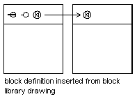
You can insert one or more block definitions from an existing drawing file into your current drawing file. Choose this method when retrieving blocks from block library drawings. A block library drawing contains block definitions of symbols with similar functions. These block definitions are stored together in a single drawing file for easy accessibility and management. For an explanation of the schematic representation shown, see Understanding How Blocks are Stored and Referenced.

For more information, see Creating Block Libraries.
You can insert blocks at intervals along a selected geometric object.
Use Content Explorer to insert blocks from the current drawing or from another drawing. Drag and drop the block names for quick placement. Double-click the block names to specify the precise location, rotation, and scale of the blocks.
For more information, see Using Content Explorer.