Active Dimensions 3 Documentation


Purchasing Information

The price of Active Dimensions 3 version 2.0 is $50 US. Active Dimensions 3 version 1.7 is also available for a lower price. Version 1.7 does not feature Outline Block Modeling. Click here to purchase your copy online.


System Requirements

Windows 95/98, Windows NT 4.0, or Windows 2000
16 bit color (24 or 32 bit recommended)
10MB free hard disk space


Screenshot


Installation

You have the option of installing Active Dimensions 3 Version 2.0 in either of two ways.

You may use the first method if you are using Windows 2000 or have the Windows 2000 installer on your machine. If you are using Windows 95/98 or NT and are not sure if you have the installer, then extract the file named ad3setup.msi into a temporary directory. If the file is not represented by a setup icon then you do not have the Windows 2000 installer on your computer.

Method 1. Extract the file named ad3setup.msi into a temporary directory. (If you use this method, all other files within the zip file are not needed.) Launch this file and follow the instructions to install.

Method 2. Simply extract the files into a permanent directory of your choice, e.g., "C:\Program Files\Active Dimensions 3\". If you use this method, you may delete the file named ad3setup.msi since it is only used by the first method. Double-click Ad3cad.exe to run the application. If you use this method, no changes will be made to your system, such as adding or modifying registry entries and/or DLL files.


Adding surfaces to your scene

Surfaces are grouped into ten categories as shown below.

Pyramids and cubes can be used as outline blocks.

Category Surfaces In Category
Miscellaneous outline block, plane, tiled plane
Extruded Regular Polygons extruded hexagon, extruded octagon, extruded pentagon, extruded triangle
Joints mechanical joint, organic joint (Both are inverse kinematics-ready.)
Diamonds round diamond, soft diamond, softer diamond, softest diamond
Platonic Solids dodecahedron, icosahedron, octahedron, tetrahedron
Cones cone, pyramid (outline block)
Cubes cube (outline block), soft cube, softer cube, softest cube
Cylinders cylinder, soft cylinder, softer cylinder, softest cylinder
Sphere sphere
Toruses torus - small pipe, torus - medium pipe, torus - large pipe

Simply click the button that categorizes the surface you want and select the desired surface from the menu. The surface will appear on the left side of the scene.


Dynamic Transformation Control

The Dynamic Transformation Control.avi file that is included with the demo version of Active Dimensions 3 gives a visual tutorial on how to use the Dynamic Transformation Control.

The Dynamic Transformation Control (DTC) is located directly beneath the ten surface category buttons and consists of six yellow arrows and three green rings that encircle a cube. The DTC is designed to facilitate 3D positioning by using a "true" 3D control. The DTC automatically orients itself to coincide with the local coordinate system of the selected surface and provides rotation, scaling, and translation that is based on the local coordinate system of the selected surface. After learning how to use the DTC, we are sure you will appreciate it.

Rotation

Left click a surface to select it. Click and hold the left mouse button on one of the three green rings on the DTC. The selected surface will automatically rotate in the same way the green ring would if it were a wheel. The entire DTC will rotate in the same way to dynamically reflect the current orientation of the selected surface. Usage of the right mouse button will cause the selected surface and DTC to rotate in the opposite direction. To increase the speed of rotation, drag the mouse horizontally (in either direction) away from the mouse-down location.

Scaling

Left click a surface to select it. Click the right mouse button on one of the six yellow arrows on the DTC and drag the mouse in the direction of the arrow. The selected surface will be scaled to a larger size in the direction of the arrow. If the mouse is moved in the opposite direction of the arrow, the selected surface will be scaled to a smaller size in the opposite direction of the arrow.

Translation

Left click a surface to select it. Click the left mouse button on one of the six yellow arrows on the DTC and drag the mouse in the direction of the arrow. The selected surface will be translated or moved in the direction of the arrow. If the mouse is moved in the opposite direction of the arrow, the selected surface will also be translated in the opposite direction of the arrow.


Standard 3D Positioning

The first three of the little round buttons directly beneath the DTC allow you to transform surfaces in a manner consistent with or similar to most real-time 3D applications. The last round button is for inverse kinematics.

  • The first button allows you to rotate a surface by clicking the left or right mouse button on it and dragging the mouse around in the area of the scene.
  • The second button allows you to scale a surface. Click a surface with the left mouse button and drag the mouse to the right to make the selected surface larger or to the left to make the selected surface smaller. Click a surface with the right mouse button and drag the mouse to the right to make the selected surface larger horizontally and upwards to make the selected surface larger vertically.
  • The third button allows you translate a surface by clicking the left or right mouse button on it and dragging the mouse around in the area of the scene. Use the left mouse button to move the selected surface left, right, up and down. While holding the right mouse button, move the mouse upwards to translate the selected surface away from you and move the mouse downwards to translate the selected surface towards you.

Inverse Kinematics

Inverse Kinematics can only be applied to joints.
Inverse kinematics in Active Dimensions 3 is simple and basic. The user does not have to know anything about inverse kinematics in order to begin experimenting with it.
Simply add a joint to your scene. Click the Inverse Kinematics button. Drag the mouse on the tip of the smaller end of the joint, and watch the joint follow the mouse in a natural manner.

Want to learn more about the use of inverse kinematics?
Open the file named "inverse kinematics.ad3". This file contains a simple robot arm that can positioned in a natural way using inverse kinematics. After opening the file, simply click the Inverse Kinematics button. Then click on the tip of the robot arm and slowly drag the mouse around and watch the arm follow in a realistic manner.


Color Selection

Click the left mouse button on the color you want in the color selection box. All new surfaces added to the scene will be the color you selected. You can change the color of an existing surface by right-clicking it and selecting Apply Current Color from the context menu.
You may also change the current color by selecting Choose Custom Color... on the Edit menu. This will display the Windows color dialog box so you can choose an exact color.


File Menu

New
If the current scene is not saved or has unsaved changes, you are prompted to save changes. Afterwards all surfaces in current scene are cleared.

Open...
Displays the Open dialog box so you can open a scene that is in the native AD3 2.0 format. You may also open an AD3 file by dragging it from Windows Explorer onto the Active Dimensions 3 window. Files that were saved with all versions of Active Dimensions 3 prior to version 2.0 are in the AD3 1.0 format and must be converted to the 2.0 format. A conversion utility is available for all registered users.

Save As...
Displays the Save As dialog box so you can save your scene in the native AD3 2.0 format.

Save Image...
Displays the Save As dialog box so you can save the current image of your scene as a bitmap.

Export:DXF...
Displays the Save As dialog box so you can export your scene as a DXF file.

Export:VRML 2...
Displays the Save As dialog box so you can export your scene in the VRML 2.0 format. If you intend to export your work in the VRML file format, you should not use the Paint Polygon Face feature. Also, you should use Boolean operations only when necessary.

Export:Wavefront...
Displays the Save As dialog box so you can export your scene in the Wavefront obj format.

Exit
If the current scene is not saved or has unsaved changes, you are prompted to save changes. Afterwards the program exits.


Edit Menu

Undo
If the last action you performed can be undone, this menu item will be enabled so you can undo the action.

Select All
Selects all surfaces in your scene.

Deselect All
Deselects any selected surface(s) in your scene.

Choose Custom Color...
Displays the Color dialog box so you can choose an exact color.

Highlight Selection
Toggles highlighting, by outlining polygons, of any selected surface(s).

Seamless Boolean Operations
Toggles Seamless Boolean Operations. When this menu item is unchecked, Boolean Operations will be performed normally. When this menu item is checked, where appropriate, Active Dimensions 3 will attempt to smoothly render the seam formed by a Boolean Operation. This feature should be used sparingly.

Create Detailed Geometry from Outline
If this menu item is checked, Active Dimensions 3 will generate detailed geometry when you create a curved surface from an outline surface.


Interactions Menu

Paint Polygon Face
Allows you to paint, using the current color, any of the polygons on the selected surface by clicking the polygon. You cannot paint polygons while all is selected.

Pick Color
Enables you to set the current color to the color of a polygon in the scene by clicking the polygon.

Position Light
Enables you to drag the left mouse button in the scene to position the light.


Render Menu

Rendering is the process of creating an image (on the screen or some other medium) of your model. The Render menu controls the way your scene is shown on your screen.

In general, 3D software can render in either of six modes. Active Dimensions 3 supports the first four of them.

  • Wireframe
  • Flat Shading
  • Gourand Shading
  • Phong Shading
  • Ray Tracing
  • Radiosity
Wireframe (orthographic)
The scene is rendered as a set of line segments that represent the edges of the polygons that make up each surface. Perspective is not shown.

Before performing any Boolean operation, it may be helpful to render the scene in this wireframe mode so that surface intersections can easily be seen.

Wireframe (perspective)
The scene is rendered as a set of line segments that represent the edges of the polygons that make up each surface. Perspective is shown.

Flat Shading
Flat shading gives a rough approximation of the scene and results in a faceted appearance of surfaces. Surfaces may look distorted and out of place, but this occurs because polygon intersections are not shown.

Surface selection is based upon the view of the scene from flat shade mode. You can only select a surface by clicking the part of the surface that would be visible during flat shading regardless of how the surface appears in gourand or phong shading.
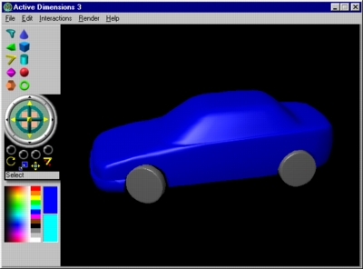
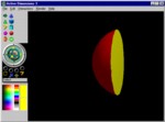
Gourand Shading
When you first start Active Dimensions 3, the current rendering mode is gourand shading. Gourand shading makes the curved surfaces in your scene appear smooth and rounded. Polygon intersections are shown during gourand shading.

Phong Shading
Phong shading is designed to give you a final view of your scene. Not only does phong shading make the curved surfaces in your scene appear smooth and rounded and not only does it accurately show polygon intersections, it also makes the surfaces appear shiny. If your scene is composed of less than thirteen polygons, phong shading will render shadows.


Help Menu

Help Topics
Displays a message box, informing the user to refer to this documentation.

About Active Dimensions 3
Displays the Active Dimensions 3 Splash screen so the user can read version information, vendor information, and program specific information. Simply click the mouse anywhere on this splash screen to close it and return to the main window.


Right-Click Context Menu

The context menu appears when you right-click a surface without moving the mouse.

Apply Current Color
Applies the current color to all the polygons of the selected surface(s).

Delete
Deletes the selected surface(s). You may also delete the selected surface(s) by pressing the delete key on the keyboard.

Duplicate
Duplicates the selected surface. The duplicate surface will coincide with the original surface. This menu item will not appear when all is selected.

Set as Front
Makes the current orientation of the selected surface be regarded as its default orientation. This menu item will not appear when all is selected.

Reset Orientation
Returns the selected surface to its default orientation. This menu item will not appear when all is selected.

Outline Blocks

Active Dimensions 3 uses outline blocks to help make modeling rounded objects easier. Using outline blocks, you can build an outline of whatever rounded object you are modeling, and then let Active Dimensions 3 automatically create the curved geometry. The process is very simple and efficient, and thereby enables you to quickly model more complex objects.

Although the basic concept of outline blocks is simple, there are some important aspects to this modeling method that must be taken into consideration. First, you must understand that Active Dimensions 3 can only automatically create curved geometry from an outline surface. An outline surface is defined as a surface that was formed solely from outline blocks. You may construct an outline surface by connecting outline blocks or by performing Boolean operations on outline blocks. In many cases you can simply connect outline blocks to build an outline surface, however there will be cases wherein you should use Boolean Operations to help build your outline surface. When you use Boolean Operations to construct outline surfaces, you should attempt to create the simplest possible geometry. For an example on how to help create simple geometry, open the file named simple.ad3. Right-click the gray outline block and select Boolean Difference (A - B): Select Operand B from the context menu. Click one of the two white outline blocks. Since the two white outline blocks have been united, they will be subtracted from the gray outline block all at once, thereby helping to create simple geometry. If the two white outline blocks were sequentially subtracted from the gray outline block the resulting geometry would be more complex than necessary.

Connect to Outline
Connects two outline surfaces to form a single outline surface. A connection will be made only if one or more polygons on the first outline matches and coincides with a polygon on the second outline. You should choose Wireframe (orthographic) on the Render menu to enable you accurately match up polygons.

Create Curved Geometry From Outline
Creates a curved surface from an outline surface. This menu item will only appear when an outline surface is selected.

Create More Curved Geometry From Outline
Creates a more curved surface from an outline surface. This menu item will only appear when an outline surface is selected.

Create Most Curved Geometry From Outline
Creates a very curved surface from an outline surface. This menu item will only appear when an outline surface is selected.

Boolean Operations

Note: Boolean operations require complex computations, and can be unwieldy.

The boolean.avi file that is included with the demo version of Active Dimensions 3 gives a visual tutorial on how to perform one of the three Boolean Operations.

Boolean operations are used to form a more complex surface from two simpler surfaces. Before performing any Boolean operation it is recommended that you be sure that the surfaces on which the operation will be performed are positioned exactly as you want them. You should view your scene from various different angles to verify this.

Active Dimensions supports the difference, intersection, and union operations.

To perform a Boolean operation, right click the first surface. This surface will be operand A. Select the desired Boolean operation from the resulting pop-up menu, and then click the second surface, which will be operand B.

The following pictures show the result of each Boolean Operation on the scene below.


Sphere interpenetrating a Cube.
Operand A = Cube: Operand B = Sphere

Boolean Difference (A - B): Select Operand B

This menu item will not appear when all is selected.

Boolean Intersection (A and B): Select Operand B

This menu item will not appear when all is selected.

Boolean Union (A + B): Select Operand B

This menu item will not appear when all is selected.

Front View
Shows your scene from the predefined front view. This menu item will only appear when all is selected. If you are not satisfied with the predefined front view, rotate your scene to the desired front view. With all selected, right click in the area of the scene and select Set as Front View from the context menu.

Side View
Shows your scene from the predefined right side view. This menu item will only appear when all is selected.

Top View
Shows your scene from the predefined top view. This menu item will only appear when all is selected.

Set as Front View
Makes the current view of the scene be the front view. This menu item will only appear when all is selected.


Tips
  • Draw your scenes from a direct front, top, or side view. This will enable you to better align your surfaces. It is recommended that you initially draw your scene from a direct front view.
  • It is easier to scale a joint by using inverse kinematics positioning to fully extend it and then scale it.
  • When using inverse kinematics, click and drag the mouse on the tip of the smaller end of the joint for greater control.
  • Inverse kinematics works better when a joint is facing sideways rather than directly towards the viewer.
    Newly added joints face sideways.
  • Use the Dynamic Transformation Control as much as possible to position surfaces, particularly during awkward scene orientation. The Dynamic Transformation Control allows greater accuracy and control than freehand 3D positioning allows.
  • Although Active Dimensions 3 lacks anti-aliasing capabilities, you can achieve high image quality by following the steps below.

    Scale your 3D model to a large size so that its outermost edges are just within the bounds of the Active Dimensions 3 viewing area. Save the image as a bitmap. Open the bitmap in a quality 2D image processor and scale it to a smaller size. Most high quality 2D image processors "anti-alias" graphics when they are scaled to a smaller size.


Sample Models

When viewing the sample models, be sure to choose Phong Shading on the Render menu for best results.


Tutorial

Click here to visit the online tutorial.


Uninstallation

If you installed Active Dimensions 3 using the first method then you may uninstall it from the Add/Remove Programs Dialog Box. If you used the second method then all you need to do to completely remove Active Dimensions 3 from your system is delete the application and its additional files.

Copyright © 2000 Robert Lee
All Rights Reserved