


Fitting a RiscPC into a PC case
Dave Holden takes out his toolkit...
Part 3 - Fitting the internals.
In the previous instalment I covered modifying the computer case, and this brought us to the stage where we are ready to start fitting things into it.
During the fabrication of the back of the case the mount for the rear of the motherboard was constructed. It now needs a single mounting pillar and a support along its front edge. This front support is very important as it must also restrain the motherboard to prevent it being pushed forward when leads are plugged into the rear sockets.
On a "real" RiscPC case this is done with a series of small lugs and clips moulded into the bottom of the case. It is not easy (or desirable) to duplicate this, although I have seen one example where this section of the RiscPC case was cut out as a long rectangle and bolted to the bottom of the new case. A much better method is to make a support of some type with a groove into which the front edge of the motherboard sits. This can then be screwed to the bottom of the case.
The method I suggest is shown below.
This mount supports and restrains the entire front edge of the motherboard and can be simply fastened to the base of the case with either self tapping screws or bolts. It is constructed from a couple of pieces of 13 mm. plastic angle, which can be purchased quite cheaply in most DIY stores.
The diagram below shows how this is constructed.
The large "L" shaped piece on the left has its vertical arm trimmed to suit the height of the motherboard above the case base. This will vary according to the case being used, and it's possible that this might be larger than 13 mm, in which case you would need to use 20 mm angle instead.
The inverted "L" shaped piece on the right is made from another piece of plastic angle by cutting the horizontal side so that it projects no more than about 4 mm. over the motherboard. The piece cut off is then used as a spacer to make the groove into which the motherboard is seated deeper.

Note that the protruding lip on the left hand end of the support has been cut away. This is necessary because the hard drive connector is very close to the edge of the motherboard in this area. The lip must therefore be cut away to clear this allowing the bracket to continue on the underside of the motherboard to support it when the drive cables are being inserted. It is easier to do this before the assembly is glued together.
Incidentally, if you do decide to make a mounting bracket of this type, before you start do first read the part of the article about making a support for the backplane. It might save you some extra work later.
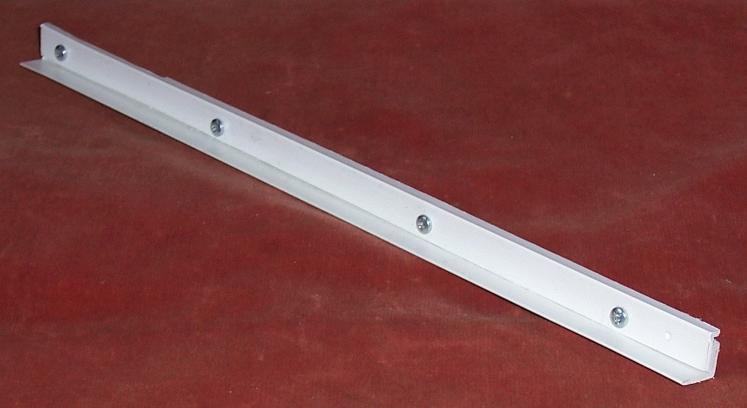
An alternative, and a method I have often often myself, is to use a PCB guide rail. This is simply a piece of plastic with a groove which is used to support plug-in printed circuit boards in electronic equipment. However, unless you just happen to have one of these of an appropriate size lying about it probably wouldn't be cost effective.
The picture below shows a typical guide rail, and also illustrates how you can very easily screw it to a small strip of wood to make a suitable support. This works very well, even though it does look rather crude, and it can be secured with small woodscrews through the bottom of the case. Using a strip of plastic angle in a similar manner is equally effective and gives a much neater appearance.

As well as the front support for the motherboard there is also a single screw which can be found just to the right of the front SIMM socket. If you have made a good support for the front of the motherboard then this is not absolutely essential, but it provides lateral location for the motherboard and also ensures a good earth to the case metalwork. Of course, if your case has a large hole in this area (as some do) this may not be possible, but it is best to fit this support if possible.
The correct method is to use a proper internally threaded pillar. This is then secured with a screw passing through the bottom of the case and the motherboard is fastened with another screw through it, just as in the original Acorn case. The cost of a pillar like this is negligible, but it's not the sort of thing you can normally buy one off. If you don't have something suitable to hand a good alternative is to use a 3 mm. set screw and either a small unthreaded spacer retained by a nut at the top or a series of nuts. The motherboard is then secured with a nut on the set screw which protrudes through it. Not quite as convenient or neat, but just as effective. The diagram below illustrates this.
It is very important that whatever method you use it is exactly the correct height. If it is either slightly higher or slightly lower than the front support then it will force the PCB to bend. You should therefore make the front mounting bracket first and only when this is made and fitted should you fit the support pillar. It is a lot easier to adjust the pillar to suit the height of the front support than the other way round. As it is most unlikely that you will find something exactly the correct height you will have to adjust it either by cutting or filing or adding packing washers under it's base.
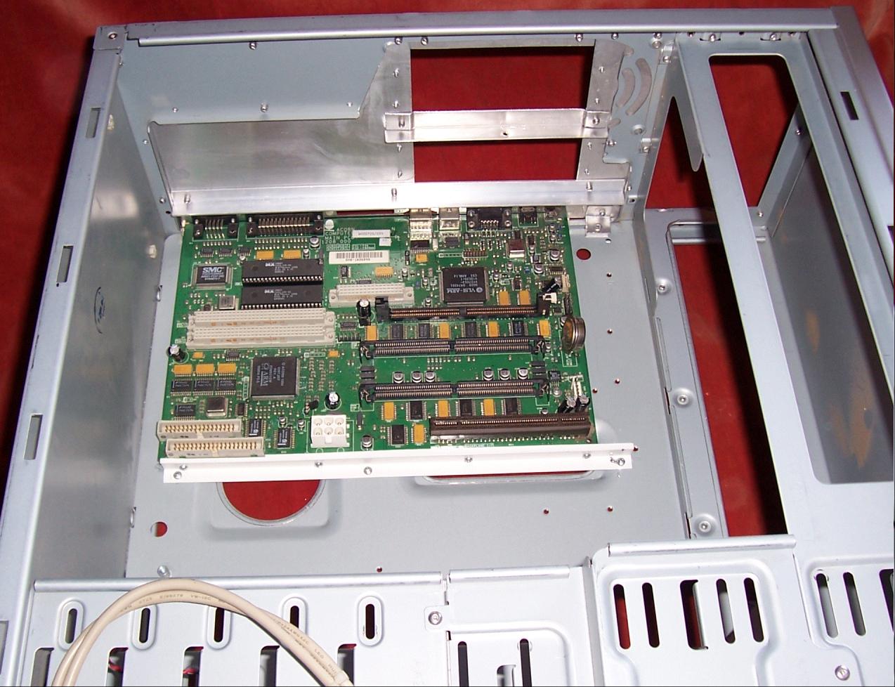
The next picture shows the motherboard fitted into the case, using a front mount made from plastic angle as described earlier. You can clearly see the cutaway by the hard drive socket and the three self tapping screws securing the bracket to the bottom of the case. You can also see that as there was a depressed section in the bottom of the case the mounting bracket had to be extended to the right to bridge this.
When you get to this stage you might want to install the power supply, processor, RAM and hard drive temporarily and power up the machine just to make sure that everything is working OK. However, there's still one more piece of metalwork that you will probably want to do before you can complete the electrics.
The backplane support
In an Acorn case the backplane is supported by the internal case structure. This obviously isn't present in a PC case. As described in the first part of this series it is not absolutely essential to do this, especially with a two slot backplane. but with a four slot backplane it is advisable because even if you never insert or remove a podule without supporting the backplane by just moving the computer the weight and leverage of an unsupported four slot backplane can put considerable strain on the socket on the motherboard.
There are two main methods you can use to achieve this. With either you will first need something to actually hold the backplane circuit board. This must, of course, be insulated. You could use a short length of PCB guide rail of the type previously illustrated, or you could use the same techniques previously described to make the motherboard support.
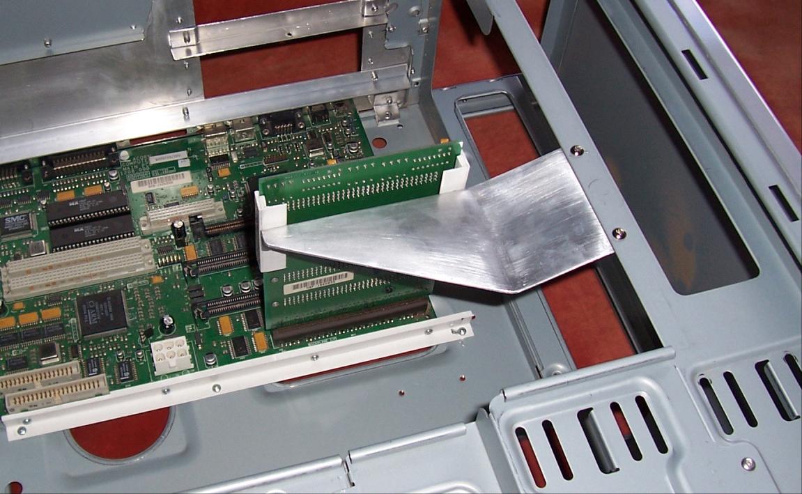
On the right of the following picture is shown a short length (about 12 cm.) of support fabricated from 13 mm. plastic angle in exactly the same way as the motherboard support except that it is made "back to front" with the mounting flange turned under the PCB. Since the dimensions aren't critical you can simply cut this at the same time as the motherboard support, gluing it together the other way about (look at the earlier diagram and imagine the large "L" shaped piece with the bottom of the "L" pointing to the left instead of to the right). You can then cut it in half to make two pieces each about 6 cm. long.

The first method of supporting the backplane was illustrated in Part 2 of this series, consisting of two pieces of 13 mm. aluminium angle bolted together to form a "T" shape. A plastic section is then bolted to either end of the crosspiece of the "T" and the bottom of the "T" is then bolted to the drive cradle. If you examine the illustration in Part 2 the method of construction should be self evident.
The case being used now has a member running from back to front just under the power supply (see earlier picture). This type of strut is quite common in PC cases and if yours has one then it can be used to brace the backplane.
The picture above shows a piece of aluminium cut and shaped to form a bracket. The following picture shows it with the plastic strip cut in two and bolted to it. This is best done by drilling the aluminium, temporarily attaching the plastic strips to the backplane with tape or a rubber band and then marking the holes in the plastic using the aluminium bracket. This ensures that they're spaced exactly the right distance apart. If they're too close the backplane will be difficult to slide in and out, if they're too far apart it will be a sloppy fit and may even slip out.
The two previous pictures should make the shape of the bracket clear. The exact dimensions will, of course, depend upon the case you are using. I have put a "kink" in the bracket so that the support is moved down from the top of the backplane, and you will probably need to do something similar. Again the amount of this "kink" will depend on the case. I have also cut away part of the bracket to give it a triangular appearance. This isn't really necessary, it just looks better.
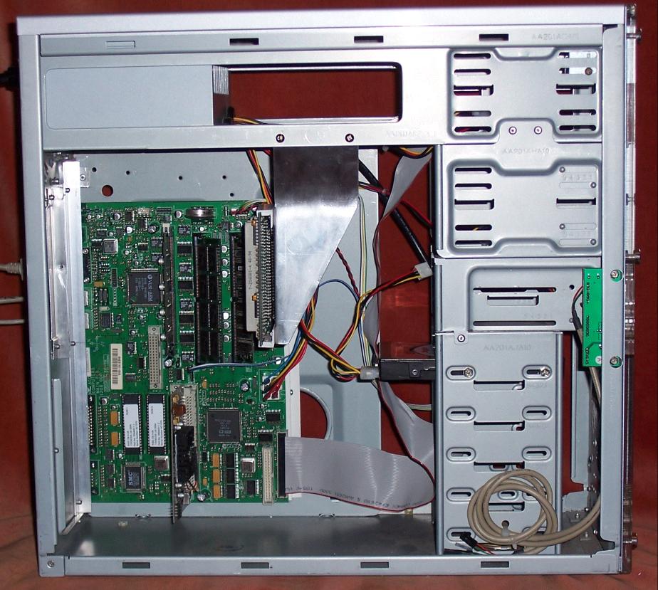
The following picture shows the brace installed, which should make everything clear. Points to note are that the bolts that attach the support to the strut on the PC case should be far enough apart to ensure that the support can't move back to front. This, and hence the dimension on the bracket, will depend upon the stiffness of the strut. Some are quite flimsy. With the case I was using the strut is quite solid so they are spaced at 5 cm.
The best way to position the support correctly is to fit the motherboard and backplane with a podule installed in the top socket. this ensures that the backplane is the correct distance from the back of the case. With the backplane held firmly in place by the podule you can then fit the support and drill the holes to secure it to the case strut. (The same method is used it you are using a "T" strut as described previously). If you don't happen to have a podule you can use then the correct distance from the outside of the case to the face of the backplane PCB is 76 mm..
I have seen backplanes supported by struts or plates to the back of the computer, but as the picture above shows the method described gives good, clear access to all three RAM sockets, much better than in a normal RiscPC case whereas bracing it to the back of the case inevitably means that the struts obstruct this access.
Finally, there is no reason why you couldn't use an aluminium plate to brace the backplane from the drive cage. Imagine the plate in the picture extended forward and bolted to the drive cage instead of extended to the side. In this case just a single mounting screw will be sufficient.
The power supply
I will assume that you are using an AT power supply rather than an ATX type, though I'll try to cover the latter in a future article.
The leads for the floppy and hard drives can be left exactly as they are, but you will need to make a power connector for the RiscPC motherboard. The picture below shows a typical motherboard power connector from an AT power supply. Almost all power supplies use standard colour codes for the various supply voltages. The ones we are interested in are;
- Red - plus 5 volts
- Black - 0 volts or Earth
- Yellow - plus 12 volts
- Blue - minus 12 volts

Some older AT power supplies use orange instead of yellow for +12 volts, but in this case they will have almost certainly used orange for the disc drive connector 12 volt leads, so it should be obvious. Otherwise orange is the code for 3.3 volts in later power supplies.
You will need two 5v (red) leads, two 0v (black) leads, one +12v (yellow) lead and one -12v (blue) lead. The remainder are not required. The best way to get rid of them is to open up the power supply and unsolder them from the PCB, but if you don't want to do this then you could simply cut them short and fasten them neatly out of the way after sealing up their ends. If you are installing an A7000 motherboard the connector is different but you will require the same six leads.
Although it is possible to purchase a connector for the motherboard they're not readily available through retail sources and so expensive for a single unit. However there are two alternative solutions.
Firstly you could use a connector taken from an actual RiscPC power supply. Removing the leads from the connector block is a fiddly job and so the easiest way to do this is just cut the leads and connect them to the leads from the new power supply, tidying the joins by enclosing them with heat shrink sleeving. If you want to hide the joins you could shorten the leads so that the joins are concealed inside the power supply casing. The advantage of this method is that you will have a "proper" power connector but the disadvantage is that you will render the old power supply useless in the process. You might not think this is important but a good, working RiscPC power supply (especially if it's the 103 watt variety) does have a significant value if sold on ebay.
The second method is to use six separate connectors and just plug them individually into the motherboard. This still looks quite neat and as you won't need to remove the motherboard power supply leads very often it's not much of a disadvantage. Furthermore the connectors required are readily available since you can use the female ones from disc drive power connectors, and these can be purchased from suppliers such as CPC or even Maplin or you can just "canibalise" any old power supply. Having soldered on the connector it is best to use some sort of sleeving over each lead. This not only serves to make it look much neater but also acts as an insulator on the outside of the connector to ensure that they don't touch together and cause a short circuit if you switch on the power supply while they're not plugged in. The following picture shows this method with heat shrink sleeving placed over each connector. As you can see it does give a neat appearance. Also in the photo are a couple of connectors of the type used.
The next diagram shows the power connections on the RiscPC motherboard. This is included in case you are starting out with a bare motherboard and so don't have an existing power plug to refer to.

Although the A7000 and A7000+ motherboard requires the same six leads as the RiscPC the power connector is different. Once again you may have difficulty getting hold of the correct type as it's slightly unusual (although as it has a 0.15 inch pitch you might be able to find something that will fit) so the best solution here might be to remove the leads from an existing A7000 power supply, especially as these have little resale value. Note that although there are only six power leads the connector is a seven way type, one connector being unused. The following diagram shows the connections.
The speaker
Before we get to the final wiring up it is quite possible that your PC case may not have a speaker, or if it does it might be a tiny piezo sounder (a little back cylinder about 1 cm. in diameter). These are now becoming quite common as they're much cheaper than a "proper" speaker and PCs almost invariably use a sound card and external speakers so all that is required of the internal speaker is the ability to emit a few 'beeps'. If you do have one of these, or no speaker at all, then you will probably want to fit a normal speaker.
You could transfer the speaker from the RiscPC, but it's a pretty feeble device, though the A7000 one is fine, but all that is required is a small 8 ohm speaker about 5 cm. diameter. If you don't want to buy a new one then almost every home has a collection of old portable radios or cassette players that haven't been used for years, probably contain leaky batteries that have done so much damage they have made the thing useless anyway, and could well have just the right type of speaker. So before you buy one take a look in the back of that cupboard where all the old stuff seems to congregate (you know the one I mean).
If the case wasn't fitted with a speaker then it may not have anywhere for you to mount one. What it probably will have is somewhere on the front of the case for a fan. This will be some sort of pierced grid and you can fasten a small speaker to this. You can either use a couple of plastic cable ties to fasten it in place or just a few blobs of silicone bath sealant, making sure it doesn't come into contact with the speaker cone.
The final connections
With all the metalwork completed, the hardware mounted in the case and the power supply ready to go there is only one final job to do, the leads for the power and hard drive indicator LEDs, the speaker and the reset switch.
The next picture shows the PC leads for these. These follow an almost universal standard, although some proprietary systems such as Hewlett Packard, Dell etc. may vary.

You can see that each connector is identified with its function. If you want to be really fussy then you could fit the same type of connector as used on the RiscPC, but it isn't really necessary as although the PC connectors are different they fit perfectly. All you need to do is switch a few wires around.
If you examine these connectors you will see that the metal inserts are retained by a small plastic "flap". This can be raised slightly with the point of a small knife or screwdriver and then the wire with the connector can be withdrawn.
The four warning LED leads on the RiscPC use a single four way connector and the speaker lead uses a two way connector, so the first job is to re-arrange the PC leads to suit. Withdraw the leads from the speaker connector which will give you a four way connector block. Now before you fir the leads superglue a small piece of scrap plastic to the outside of the connector. The purpose of this is to thicken the connector on one side so that it can't be inserted the wrong way round. Remove the two leads from the connector marked "HD LED" and fit them to the front two slots in the connector, yellow at the front, white next. Now remove the two leads from the connector marked "Power LED" and fit them to the rear two leads in the connector, white at the back, blue in the 3rd slot. You should now have something that looks like the next picture.

One of the two way connectors removed from either the HD or power LED leads can now be fitted to the speaker lead. The diagram below shows the layout of the this group of connectors on a RiscPC motherboard. The orientation of the speaker is unimportant, but the two LEDs do need to be connected the right way round. However, if the the colours of your leads don't correspond with those shown don't worry, if they're fitted the wrong way round nothing will be harmed, the LED simply won't work so you can try the lead the other way.

The A7000 and A7000+ have a similar set of six connectors at the front corner of the motherboard divided into a block of four and a block of two. However, these are not quite the same as the RiscPC. The block of two is at the front, and this is not the speaker connector but a 12 volt supply for the fan. If you plug the speaker into this you'll just fry it. The block of four is identical to the connectors on the RiscPC so can be treated in exactly the same way. The speaker connector on the A7000 and A7000+ can be found at the rear right hand corner of the motherboard, just in front of the reset button, labelled "LK5".
If you have a Series 3 RiscPC motherboard (the one with built in 16 bit sound) then you can connect the Reset button to the two pins shown in the diagram below. The connector on the end of the lead should just push on to the two pins. If you don't have a Series 3 RiscPC then if you want a working front panel reset button you will have to solder a pair of leads onto the middle two pins of the actual RiscPC reset button where they protrude under the PCB.
<

Finally....
I have now covered just about everything you need to know to fit a RiscPC or A7000 motherboard into a PC case. Obviously exactly how you proceed will depend upon the case you are intending to use. Some are easy, some are difficult, and some are very difficult. The case described in this article was fairly straightforward and so almost anyone with the most basic of tools should be able to manage such a conversion.
In general tower cases are easier than desktop cases, and the easiest of all are old AT full tower cases. These will have the correct type of power supply and mains switch which can save quite a bit of fiddly work.
I haven't described installing and wiring up the peripheral devices such as floppy and hard drive, CD ROM etc. There's really nothing difficult about this, in fact it's much easier than doing the same job on a RiscPC.
One final point. In view of my earlier article on RiscPC cooling you might have wondered why I haven't made any mention of it here. The principle reason is that with a large PC case, especially a tower case, without all the internal plastic struts and obstructions of a RiscPC case there is so much room for the air to circulate unimpeded that there really is no cooling problem. Most RiscPC cooling problem are caused by the design of the case, not because the components require any special cooling.
To finish off here is a picture of the computer. At this time the only things still to be fitted were the floppy drive and CD ROM. It was actually running when this picture was taken undergoing soak testing of memory and hard drive.
Dave Holden