|
Planning & Installation by VacuDuct Ltd
Company: VacuDuct Ltd |
Guide to planning and installation of a Vacuduct system.
A Vacuduct built in vacuum system consists of 3 key elements. The power unit, the fixed ducting and the flexible cleaning hose. Correctly planned and installed it will give many years of satisfactory service.
The system can be installed into virtually any property whether under construction or undergoing renovation. It is usually possible to install a system into any existing house without damage to existing decoration, walls and or floors.
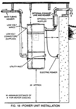
1.The power unit. The power unit is ideally located away from the main living areas. This may be an integral garage or basement, alternatively space may be found in the utility room or a cupboard under the stairs.
Installation of power unit. If it is necessary to fit the unit in a cupboard ventilation must be provided. Louvered doors will achieve this.
If the unit is not in the garage provision should be made to vent the exhaust to outside atmosphere. The reason for this is twofold. The exhaust air is hot from passage around the motor and needs to be expelled remotely to avoid overheating the motor. Also the exhaust air contains micro-particles of dust which should be released to atmosphere.
The exhaust pipe is made using 50mm PVC duct. A vent flap should be provided to stop ingress of debris from outside. As shown a muffler can be fitted in the exhaust run. In addition an intake muffler can be fitted to the top of the power unit. This reduces the higher frequency noise from the air intake of the motor.
At 1 mtr. the un-silenced power unit will typically produce noise in the range of 68 to 70 decibels. Motor speeds are in the order of 18000 rpm so a secure fixing for the wall-mounting bracket is required.
Typical power unit installation in garage with exhaust vented out side
2. The fixed ducting. 50mm dia. PVC ducting is used to connect the power unit to the inlet valves. The ducting is often routed through the loft and down to the inlets. In a new build situation first fix is usually carried out when timber studs and floor joists have been installed but not covered up. Ducting can be built into studded walls before dry-lining is fixed. With solid walls ducting can be routed down inside cupboards and use can be made of voids adjacent to soil pipes which will subsequently be "boxed in".
With beam and block floors it sometimes feasible to run ducting under the beams. With suspended timber ground floors use may be made of the void beneath the floor.
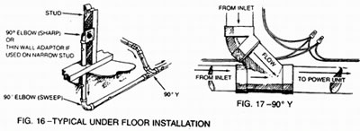
Push fit bends, junctions and fittings are pre-formed in PVC and joints are made using solvent adhesive. To ensure a "clog free" installation junctions between branch lines and the main ducting route are to be from the side or above. This is to avoid creating traps which debris can be caught in.
Behind each inlet valve a special "sharp" 90-degree elbow is fitted. This creates a trap. Any large item that would cause a blockage will be caught by this trap and can be removed from the system via the inlet valve. Every other bend in the ducting is a slow radius bend to ensure a smooth flow back to the dirt collector bin.
Automatic switching for the power unit and avoids the necessity of going to the power unit to switch the power unit on. The power unit is activated when the cleaning hose is inserted into the inlet valve.
Inlet valves are usually fixed to previously installed mounting plates when plastering has been completed. Inlets are approx. 80mm wide by 120mm high and are available in both plastic and metal in a selection of colours. Low voltage wires are connected to terminals at the rear of the inlet prior to installation.
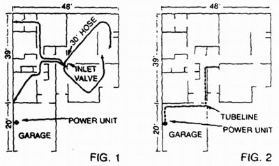
The number and position of the inlet valves is dictated by the length of the cleaning hose. 9 mtrs. is the norm, longer than this and air friction losses through the hose reduce efficiency. From a central position it will be possible theoretically, to reach an 18-mtr diameter circle. It is not therefore necessary to install an inlet in every room. From a central hall or landing position it is usually possible to reach into two or three rooms from just one inlet point. Compromise is sometimes required between the ideal inlet position and the feasibility of connecting to the ducting.
Although normally wall mounted at a convenient height, slim-line, metal, floor-mounted valves are available and can be used where wall mounting is problematic.
3.Hose and attachments. As mentioned above the standard cleaning hose is 10 mtrs. long, and weighs 1.5 kilos. Hoses are 35mm diameter, crush-proof spiral bound plastic. One end is finished with a 35mm cuff, which incorporates a metal ring. This end is inserted into the inlet valve and the metal ring completes the low volt circuit automatically switching the power unit on.
The other end of the hose is finished with a curved, chrome steel and plastic handle. The user fits a plastic or metal wand to this end of the hose. Various cleaning tools can then be fitted to the wands; telescopic metal wands are available to allow adjustment to avoid bending on the part of the user. Plastic wands are of course lighter.
On/off hoses are available. With these the low voltage current is carried up inside the hose to a switch at the curved end of the hose. This eliminates the need to unplug the hose when pausing to answer the phone etc.
A rack is provided on which to store the hose when not in use. This can be fitted inside a convenient cupboard.
A recent development is the Vacpan unit. This is a flush-mounted, floor level inlet that can be fitted in areas of hard floor finishes. It allows users to sweep the floor clean but eliminates the need for a dustpan. Opening the Vacpan with a foot automatically switches on the power unit and the debris on the floor is sucked away to the dirt collection bucket. The Vacpan is deactivated by closing the valve with ones foot.
Detailed installation instructions are provided with every DIY kit or can be down loaded from http://www.vacuduct.co.uk/
|