|
|
|
|
|
|
The Results Screen, as shown in Figure 11, displays all of the relevant information about the anchors selected, after calculations have been made based on the data entered. The upper left-hand corner of this screen displays all of the selected anchors and puts; (1) a red "x" next to them if they do not meet every condition of the designed connection, (2) a green check next to them if they do meet every condition of the connection, or (3) a green dot next to them if they are acceptable and their embedment depth is changed to standard embedment. Information about the connection requirements that are not met (i.e. the red "x") is also available on this screen. Finally, the Results Screen also provides some basic information about how to install the selected anchors. |
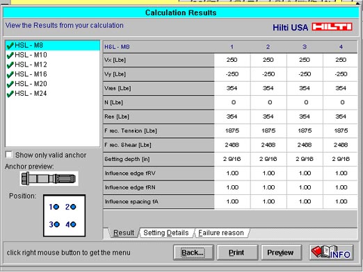
The results on the Results Screen are organized into three subscreens which are accessible by clicking the tabs located just above the OK, Print and Preview buttons. From left to right, the tabs are titled as follows:
When the tabs are clicked, the pertinent information relating to that tab is displayed on the screen. As you switch tabs, however, the left side of the screen continues displaying the names of the selected anchors, which of the anchors meet or don't meet the design requirements, a drawing of an anchor, and a diagram of the selected connection configuration. When you are finished viewing the results in the Results Screen, you may click on the Back button to return to the Main Menu Screen, the Print button to print the current results, or the Preview button for a preview of the printout. This subscreen, displayed at the right side of Figure 11, shows a table of numbers. Horizontally, it lists each one of the selected anchors (i.e. if it is a six anchor configuration, it will list them in columns 1-6, each number representing a position). In rows, it lists the loads that you imposed as part of the design problem, the resultant loads for each anchor , the published allowable for each anchor, the setting depth of each anchor and the associated edge distance and spacing influence factors. 3.3.2 The Setting Details Subscreen The Setting Details Subscreen, shown in Figure 12, displays information for proper anchor installation. Under the Setting Tools heading, this screen tells you the recommended Hilti drill bit, the recommended Hilti rotary hammer drill, the width across flats of the hex nut (wrench size) and the tightening torque. This screen also tells you the diameter of clearance hole in the base plate necessary for an in-place fastening and the minimum member depth (i.e. minimum base material thickness). |

3.3.3 The Failure Reason Subscreen The Failure Reason Subscreen, shown in Figure 13, displays the reason(s) why the selected anchor did not meet the requirements of the input design data. |

| [ Previous ] [ Next ] [ HAP User's Guide Table of Contents ] |
| [MAIN MENU] | [TABLE OF CONTENTS] | [SELECTOR GUIDE] |
| [FIRESTOP PROGRAM] | [HAP PROGRAM] | [DECKING PROGRAM] |
| [HILTI WEB SITE] | [SEARCH] | [SUBMITTAL PACKAGE] |