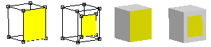
| The Object/Point button |
| Just below the coordinate axis button row there is a new row
of three buttons: |
| There
are two buttons that you will find helpful when selecting points, edges and
faces. They control whether you can select front facing
|

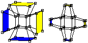
Connecting Meshes |
| You can attach two separate meshes to create a single, connected
mesh using the JoinSolids, Add Points/Edges and Add Faces commands. |
|
|
Merging Points |
| You can merge separate points into a single point with the Edit->MergePoints
command. First select the points that you want merged. It is best if they
are very close to each other to begin with. Then apply the Edit->MergePoints
command. A dialog appears where you can enter the maximum distance allowed
between pairs of points. Click OK and all eligible pairs will be merged. |
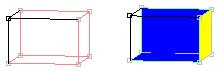
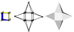
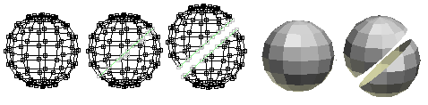
| Connecting
Meshes (2) |
|
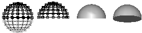
You can also use this technique to connect two meshes. It works best if
the connecting point sets are similar in size and number. For example connecting
half of a Sphere that has 12 longitude lines with a cylinder with 12 sections
around is a snap. |
|
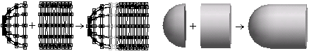
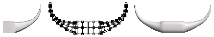
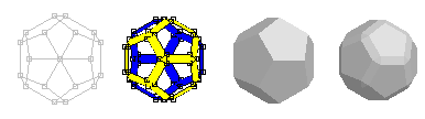
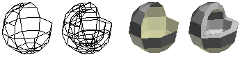
Connecting Meshes (3) |
|
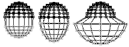
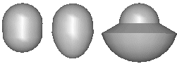
You can often build one half of a symmetrical object, then mirror it with
Build->Mirror, and join the two halves into a single mesh with Build->JoinSolids.
Then position the two halves close together, select the adjacent points
and use Edit->MergePoints in the Point Editor to make a seamless connection.
This merged object was then smoothed one time to round off the corners. |
|
Point and Line Parameters |
|
| When you are in Point When you and in Edge |
|
Face Extrusion and Manipulation Tools |
|
| You can manipulate selected faces
in a variety of ways using the lower group of buttons in the toolbar.
They can be used to build very complex models from a small number of cubeish
shapes using the box modeling method. |
|
|
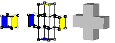
You use this button to extrude all of the selected faces. Each
face is translated in the direction that it faces, either out or in, and
new edge polygons are added to connect the face to its original edges. |
|
|
|
| Similar
to the extrude tool, the extrude-connected tool extrudes selected
faces in a Mesh. However adjacent selected faces remain connected. New
faces are only added to the edges between a selected and an unselected
face. |
|

|
|
| The
6 faces on the solid on the left are shown extruded and extrude connected
above. |
|
| This
button rotates each selected face around its center. It's
most useful when the selected faces aren't adjacent. |
|

|
|
| You
can scale selected faces using this button. |
|

|
|
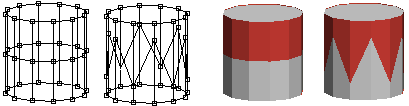
| This
one will replace faces with a peak. |
|
|
|
| The
bevel tool is useful for adding faced corners
to surfaces. You can bevel both faces and edges of any mesh. Selected edges
are turned into new faces, cutting toe corner off of the original model as
shown below: |
|
|
|
| Selected
faces are handled as a group. Edges between a selected face and an unselected
face are beveled but edges between two adjacent selected faces are left
alone. |
|
|
|
| The
inset tool is also useful for adding faces
to surfaces. Each selected face is replaced by a smaller version of itself
and new faces that connect it to the original edges. This is an easy way
to add more detail to a particular part of a model, or to make a hole for
a door, window, or eyes. |
|
|
|
| You
use the shell tool to add thickness to the walls
of a Mesh. To make a shell simply click on a Mesh or a Subdivision
Object and drag the mouse. The basic Mesh cannot be completely closed.
It must have at least one "missing" face. |
|
|
|
| The
bump tool raises all the selected faces up
on a bump. |
|

|
|
| If you
want to cut a slice through a model you'll find the cut
faces tool quite handy. It slices through edges and faces when
you click-drag the mouse across an object. If you slice all the way
across an object as shown below you can then use the Edit->LoopCut command. |
|
|
|
| You can
divide a face into two by clicking on one vertex and dragging to another.
The connecting line will snap to a vertex when you click nearby. Or
you can disable the snapping if you press and hold the Shift key when
applying a cut. You may want to disable the back facing edges from
being cut as well by turning off the |
|
| The slide tool lets you slide a point along an edge, or extend the edge. Just click on a point and drag the mouse in the direction of one of the edges that enters it. This will select the active edge and shorten it. If you want to lengthen it instead just keep dragging but in the opposite direction. | |
|
|
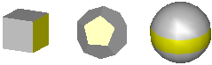
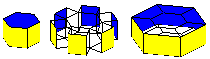
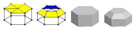
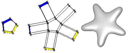
| When you use these face manipulation
operations you often follow with one or more applications of the subdivide
operator to build more complex shapes. For example, start with an extruded
pentagon, select all 5 outer faces, extrude them, and smooth to make a starfish: |
|
|
|
Face Editing Commands |
| Anim8or has several other useful face editing commands. You
will find them under the Edit menu in the Point Editor. |
|
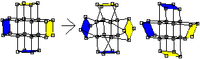
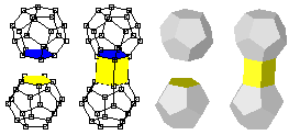
The bridge commands allow you to do
several useful operations. To use it you first select two different faces.
They have to have the same number of edges but can belong to different Meshes
if you want. The Edit->Bridge command then will connect the two selected
faces with new faces connecting each edge of one face with the corresponding
edge on the other face. You can poke holes through a Mesh: |
|
|
You can connect two parts of a Mesh to form a bridge: |
|
|
And you can join two different Meshes into a single mesh: |
|
|
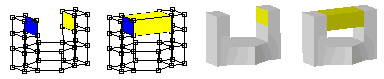
The flatten command does just what
it's name suggests: it flattens groups of selected faces. All the vertices
of each group are projected onto a flat plain. You can choose the group's
average face direction or the X, Y, or Z-axis. Flattening is quite useful
when you need a level base for a model, and can be use with the merge face
command to help simplify your models. |
|
|
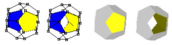
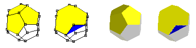
The merge faces command combines
groups of selected faces into a single face. You can simplify areas of your
models that are too detailed this way. |
|
|
You have to be careful to keep the faces convex and relatively
flat or they may not render properly. Convex faces are those that don't
have any points inside their outer boundary. Faces with interior points
are called concave and can cause rendering errors: |
|
|
In the example shown above three pentagonal faces are merged into one
big face with 9 sides. It is concave and doesn't draw properly as a result.
It's easy to see in this example because of the stray back facing part
is blue when it is selected. Other times it may not be as obvious what
is wrong. |
|
If you are working with a Subdivision object this is not as important.
The faces that you are editing aren't drawn in your final object. Subdivision
will smooth the mesh making it much better formed along the way. |
Misc. Commands |
| There are several miscellaneous commands in the Point Editor that
you will find useful. One group helps you make certain useful of selections
that could otherwise be quite tedious. The other group modifies objects
in various ways. |
| Selection
Commands |
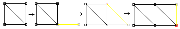
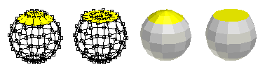
| A
Quad Loop is a chain of adjacent quads, or 4 sided faces, that
are attached across opposite sides. The Quad Loop Select
command extends selected edges along quad loops as long as there are exactly
four faces joined together at each vertex. For models like the sphere
below this results in a closed ring around a latitude line. For vertical
edges it only extends to the poles since there are more that four faces sharing
the pole points. The Quad Ring Select commands work on chains of adjacent quads, or 4 side faces. When a quad has a selected edge, the opposite edge is also selected. This is repeated until all quads in a "ring" are selected, or until a face without 4 faces is encountered. (Selections are shown in red here to make them better visible against a white background.) |
|
| You will
find these commands under the Edit->Select menu. |
| Editing Commands |
| These four commands are useful for adding detail to part of a Mesh. Connect Edges adds new edges between the centers of any selected edges that share a face. Cut Edges splits each selected edge into two in the middle. Subdivide Faces divides those faces into several smaller faces. It does this by adding a new point in the center of each selected face and connecting it to the points of that face. |
| Loop
Cut splits a mesh into multiple parts along closed loops of selected edges. |
| These
commands are under the Edit menu. |
| This page was last
updated on August 10, 2003 |
Copyright 2003
R. Steven Glanville |