3 Object Editor Basics


The object editor is where you create and modify new 3D objects. You enter the object editor by default when you run Anim8or. You can enter it at any time by selecting Mode->Object in the menu.
The basic screen is shown below. On the left is a toolbar. It has icons that represent the most common operations that you will be doing. It allows you use to change the mode that you are working in, add basic primitives, etc. You use the menu at the top of the screen performs less commonly needed actions.


The object editor has four modes: edit, viewpoint, axis, and point edit. You change the mode you are currently working in by clicking one of the topmost four buttons on the toolbar. This will also change the lower part of the toolbar to display buttons appropriate for that mode


Object/Edit mode button. This is the initial mode that the object editor starts in.

Object/Viewpoint mode allows you to pan, scale, rotate, and size-to-fit any or all of your views of your workspace.

Object/Axis mode lets you move an objects pivot or origin.

Object/Point Edit mode allows you to manipulate individual or groups of points, edges, and faces.

Object/Edit Operations

In Object/Edit mode there are some buttons just below the six small buttons on the toolbar that you use to manipulate components of your objects. Your actions only affect the selected parts of an object.

You can select something by clicking on it when you are in select mode. This button puts you in select mode. You can temporarily switch to select mode at any time by pressing the Control and Shift keys.

You can also select components by dragging a rectangle around them in drag-select mode.

These buttons allow you to move,

rotate,

scale non-uniformly, and

scale the selected components with your mouse.

You can also add and edit splines by adding straight and

curved segments. Splines are also sometimes called paths since they can be used as a path for motion.

texture coordinate editing tool. You use this tool to interactively apply texture coordinates to selected objects. It adds an overlay to the screen that is similar to the arc-rotate tool used for changing your viewpoint but for textures.  The yellow square represents a texture's basic size. You can move the texture around on your objects with the right mouse button, and you can rotate its orientation with then left button. The middle button scales textures. Remember if you don't have a middle button you can hold the Alt key down and use the right button instead.


Basic Objects

You can add new objects to Anim8or in two ways. The first is to import meshes for the 3ds, lwo, and obj file formats. You use the object->import menu item to do this. The second way is to start with one or more built in primitives. The lower part of the Object/Edit toolbar has several icons for adding new primitives.
 
This button allows you add spheres to an object. First click on it. Then move the mouse to where you want the sphere to be added. Click and drag to create a sphere of the size you desire.

If you want to add several spheres, use the right mouse button. Using the left button returns to select mode after adding a single object.

Double clicking on the sphere brings up a dialog where you can change the sphere's properties from the default.
 
This button adds cubes. You can divide them into as many subdivisions in each axis as you like by double clicking on a block to view its properties dialog.
 
This button adds cylinders. You can taper them, leave the ends open or closed, and set the number of divisions used to make them in their properties dialog.
 
Add various platonic solids and other built-in solids with this button. You can set the current solid type using the build->primitives menu.

This button adds unfilled polygons to an object. They are built as an editable spline so you can make a lot different shapes starting with the right polygon. Spline can be filled, extruded, lathed, edited, etc.

To set the number of sides, use the build->primitives->n-gon menu item.


You create True Type text objects with this button. Just click somewhere in a window and start typing. If you want to change the properties, double click on the object. You can use any font and style.
 
Each letter it a single spline (possible with multiple parts, like the hole in an O), and the whole string of characters is grouped together. You can extrude text objects directly using the Build->Extrude menu item.
 
You can also convert a text object into a group of general-purpose splines using the Build->Convert_to_Spline menu item.

This is the modifier button. Use it to add modifiers, which can bend, stretch, warp and twist another object into many new shapes. Modifiers are covered more fully in a later section of this chapter.
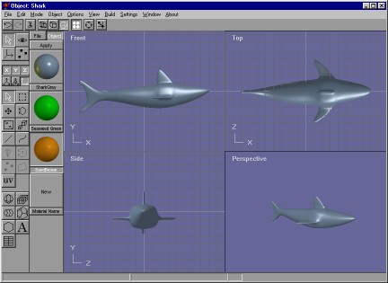
Each object in Anim8or has its own coordinate system. Its pivot is located origin. When you scale or rotate and object it is done using the pivot. When you are in wire frame mode, the pivots of selected objects are shown as red-green-blue axes as in:

You can move and rotate pivots by using edit/pivot mode.

Mesh vs. Parametric Components

There are two kinds of components in an Anim8or object, parametric and mesh. Parametric components are defined by a small set of numeric values. These values are used to build a viewable mesh whenever they are displayed. You can edit these parameters by double clicking on a parametric component, which will generate a new mesh for display. But you cannot modify the mesh directly. Some parametric components are the sphere and cylinders described above.
Meshes however can be fully edited, smoothed, etc., even at the point or face level. You can convert parametric components into meshes with the Build->Convert_to_Mesh menu item. It is easy to see if an object is a mesh or not by selecting it. In a filled view selected parametric components are enclosed in YELLOW bounding box and meshes in WHITE ones. In a wire frame view parametric components are shown in yellow lines and meshes in white or some other color lines. The four spheres below show the same geometry. The first and third are in their original parametric form, while the second and fourth have been converted into meshes.

Once a parametric component has been converted into a mesh it cannot be reverted.

Object Materials


You can view the materials in an object by displaying the material toolbar from the Options->Materials menu. Each named material is shown applied to a small sphere. Double clicking on the sphere brings up the material editor dialog allowing you to change that material’s properties.

The selected material is shown as a depressed button with a white name. You can set the basic material for any selected component by clicking the Apply button.


The Object button shows the current object's materials.


The File button shows the project's global materials, those that are shared among all objects in an entire project. You should add materials that are common to several different objects to the global list to help manage them easier.

If you want to define a new material, simply double click on the New button at the bottom of the list.

If there are more materials that can be shown, you can left click in the material toolbar and drag up or down to scroll the list.

Materials are discussed in more detail in chapter 10, Materials.


Splines

You use the spline  and line  buttons to manipulate splines. To add a new spline, you must first deselect everything. Then select either the spline or line button and click and drag to place the first segment. The spline will be drawn with a white pick box at its root and a red one at its head like this:

The red box also indicates that the spline is extendable. You can left click on it and drag to add more segments:

Once you have built all of the segments you need, go back to select mode and double click on the spline to bring up its property dialog and uncheck the extendable check box. This prevents the accidental extension of your spline when you are trying to modify it in some other way. Go back to spline mode and your spline will look like this:

Now if you reselect the spline button you can click on knots and display their control points:

You can drag the knots to new locations, and change the positions of the control points to alter the shape the spline. Double clicking on a knot will show the knot dialog where you can change the knot into either a smooth knot or a corner.
Double clicking on a segment will highlight that segment and let you set the number of straight lines used to draw it:


True Type Fonts

When you click on the text button  you can add text to an object. Click in a view window and a text cursor will appear. Type some text and it will appear as an outline in the window. Double click on the text and the text dialog appears. You can change the font, make it bold or italic, and set its size. You can always resize a text object but this isn't always the same as changing its initial size with the font properties dialog. Larger fonts are sometimes generated with more detail.

You can also fill and extrude text. Use the Build->Fill and Build->Extrude menu items:
 
When they're filled or extruded, text objects are converted into meshes. Afterwards, you can do anything to them that you can to an ordinary mesh.

Filling

You can convert any closed spline into a flat, filled mesh. Just select that spline and apply the fill operator using the Build->Fill menu item. The spline should not cross over itself or it will not fill. To fill a spline, simply select it and the select the Build->Fill menu item.

You can also build complex splines consisting of multiple independent curves. Interior closed areas are filled as cutouts. To build complex splines, select several basic splines and apply the Build->Join_Splines menu item. For example:

Since text items are actually a group of (possibly) complex splines, text can also be combined with splines and filled. First select the text and convert it to splines with the Build->Convert_to_Spline menu. Then ungroup the string of characters with Build->Ungroup. Finally select the spline along with all of the individual characters and combine them into a single multiple spline with Build->Join-Splines. Then fill the result:


Extrusion

Two more operations you can do on splines are extrusion and lathing. Both create a three-dimensional mesh out of a spline, but each in a different way. An extrusion sweeps the edges of the spline along a path (straight or curved) while lathing spins them around an axis.
To extrude a spline simple select it and choose the Build->Extrude menu item. This will display a dialog with several parameters that you can set, such as whether to cap the ends and which direction to extrude. One option is to extrude along another spline. When you choose this option, you will be prompted to choose the spline after you leave the dialog. That's the Some extrusions are shown below:
 
Note: The "center point" for the extrusion is the initial origin of your spline. Make sure that you create the spline around the origin or the results won't be what you expect.
You can also extrude text. Just select it and choose Build->Extrude:


Lathing

Lathing creates a solid surface from a spline by spinning it around an axis and converting the area it sweeps into a mesh surface. It can produce a variety of different objects depending on the shape of the spline that you lathe. If you lathe a closed spline you can create wheels and donuts. If you lathe an open spline, you can build wine glasses, pots, and vases:
 
Since you can apply texture coordinates at the same time that you are lathing a spline, it is easy to build things with detailed colorings.
You use the Build->Lathe command to lathe a spline. This displays the dialog:

The Axis section selects which axis will be used to do the rotation. You can control the behavior of the end points of an open spline with the settings in the Start and End sections. The three objects below are all lathed from the same spline, but the starting point (the one at the top, not the red one) is handled differently in each case. Open leaves the points at the beginning and end in their original place. Closed adds a new point on the axis at the same level as the end point and connects to all the end points creating a flat top or bottom. Point moves the splines end point precisely to the axis and then lathes the spline.

Open, Closed, and Point modes used at the Start

Modifiers

Modifiers allow you to stretch, bend, twist, and warp meshes into an endless variety of alternate shapes. To use them you create a modifier object and bind it to an existing mesh with the Build->Modifiers->Bind menu item. You can double click on the modifier to bring up its property dialog and change its behavior. The effect it has on the target mesh is shown in your object views. When you are satisfied with the shape, select the Build->Modifiers->Effect menu item and the mesh will be transformed into its new shape.

Here is an example of a cylinder modified by a twist, taper, skew, curvature, and a bend modifier. Modifiers preserve texture coordinates and other properties bound to points on the object.

Mirroring

You can also mirror an object using the Build->Mirror menu item. This builds a mirror image of the original object, a duplicate with the points reflected to the opposite side of the X, Y, or X-axis. These hands are simple mirrors of each other:

You often can model one half of a symmetric object easier that the whole. To build the whole, mirror the half model and join the two together.

Subdivision

You use subdivision to round the corners of basic shapes and to give more detail to the model. Anim8or can subdivide any mesh. Just select the objects that you want subdivided, and select Build->Subdivide from the menu. Each time you do this you will round the corners a bit more, and multiply the number of facets by four. So be careful, or you'll create a very large model to manipulate!

Note: Subdivision used to be called smoothing in earlier versions of Anim8or.
There is a technique called box modeling that you can use to model complex objects that begins with a simple box. You bevel, extrude, resize, and warp a few flat faces until you make a rough form of your desired object. Then you apply subdivision, and viola! You have a nice model. The following models were made in Anim8or using box modeling:
 
Not a bad hand considering it was modeled by 24 simple cubes! You can learn more about building the box shapes in the section on Object/Point Editing.

Subdivision Objects

You can convert a Mesh into a subdivision object with the Build->ConvertToSubdivided command. You edit Subdivision objects just like regular meshes, but they are automatically subdivided as you work. This is a far easier way to model than to continually apply subdivision operations to try and see what your model will eventually look like. Selected faces are shown as transparent windows revealing a further refined model inside:


When you resize or extrude a face the internal smoothed view changes shape to follow. (You only see this view in the Point Editor. All other places your model will be shown as fully subdivided images.)
You can convert a Subdivision object into a Mesh with the Build->ConvertToMesh command. It will be converted at the subdivision level that you are using to view it in the working views.
Another very important advantage to Subdivision objects is size. Subdivision objects are stored in the undivided format that is many times smaller than the final fully divided model. You can control the level of subdivision used on the screen and in the final image by double clicking and editing the properties dialog.

This page was last updated on March 15, 2003
Copyright 2003 R. Steven Glanville