
To 'Morph' means literally to change form. In computer animation it is 'morphing' that helps up make the impossible possible. Movie and TV commercial makers use computer generated morphs to bring apparently inanimate objects to life. The dancing juice carton, facial expressions of animated characters and 'bendy' cars are all produced by morphing a basic shape.
In the context of computer animation software packages you start with a model of the basic shape or object and then use the tools of the software to distort it in to a number of 'key' shapes. Then during the animation phase the key shapes will be joined up to give a seamless change from one form (morph) to another.
An animator could use the morphing technique as the only method of animating the models in a virtual scene. However there are much more efficient ways of animating simple 'rigid' motion (i.e. keyframes for position, rotation, scale etc.). Even for the gross actions of articulated figures there are better ways to do it. A 'skeleton' around which a wireframe mesh is attached makes realistic motion much more readily attained. Add some 'mathematical musculature' and a lot of the drudgery required to set up all the 'key' morph shapes is avoided.
However there are cases were morphing is unavoidable and it often is the 'best' way to achieve some effects (the dancing juice carton in TV ads. is a prime example). An ideal computer animation package provides to its user all these different techniques.OpenFX indeed does this and in this tutorial we will look at the basic use of morphing. (Subsequent tutorials will look at Skeletons).
In the context of OpenFX morphing is heavily associated with the Modeller module. To animate the morphed shapes require simply the setting of a few switches in the Animator and the adjustment of at which time the key frames occur for the Costume timeline.
OpenFX supports two methods of morphing:
We will start by looking at type (1) morphing. However before getting in to details let's consider the basic fact:
All models are build from triangular facets attached to vertices positioned in space.
The facets (faces) give the surface attributes and are what is actually visualised. In the context of morphing we might want to change their colour or texture during the morph. The shape of the object is dictated by where the vertices in the model are located,so moving the vertices will change the shape of the model. For example we could easily change a spherical shape into a cubic one by moving the vertices in the sphere. A change of shape is probably the most common use of the morphing technique.
To get the ball rolling we will look at this simple morph Sphere >>> Cube >>> Sphere...
So we need modes of a sphere and a cube, and they must have the same number of vertices. Now obviously you can make a cube with only 8 vertices but this would not make a very good model for a sphere so we might as well start with the sphere. This sets a very good principle when using the morphing technique:
Start with a model of the object that requires the greater number of vertices to represent its shape
You can then produce the shape of the second model by moving the vertices from the first model into positions that best represent the shape of the second model.
Note that we don't suggest building the second model from scratch and adding vertices to it until it has the same number as the first model. We start with the first and produce our representation of the second from the first model - this is a very important principle of morphing.
The reason for this is that the animation software (OpenFX) has a numbered list of all vertices in the model and it associates vertex 1 from model 1 with vertex 2 from model 2, vertex 3 with vertex 3 etc. etc. In the animation phase vertex 1 from model 1 moves to the position of vertex 1 in object 2 etc. etc. Thus, just supposing we morphed two similar cubes (you would expect not to see any changes) however if the list was reversed so that the top right back vertex was first in the list for cube 1 but the bottom left front vertex was first for cube 2 then as the morph progresses in the animation we would see the cube appear to turn itself inside out, which is probably not the effect we were looking for.
Now back to the example:
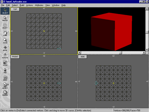
Start OpenFX and switch to the modeller. Use the build primitives menu command to build a cube, (I know I said earlier we would start with a sphere but in OpenFX it is actually easier to do it the other way round. - we must just remember to add a lot of vertices to the cube.) Hopefully you will start with something like this:
Use the Build Primitives Modless Dialog to add a simple cube which is centred on the Yellow Cross (Centre of model)
Modelling continued...
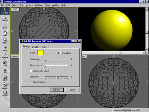
The basic cube has far too few vertices to make a convincing Sphere so we must add a large number of vertices to the basic cube. This easily done by subdividing every face in the cube a couple of times. Make sure all the vertices are selected (Coloured Yellow). Use the Actions/Subdivide (<ctrl>+V) menu command three times to give a cube with 768 faces. It still looks like a cube but now has enough vertices for us to distort it into a Spherical Shape. After division it should look like:
I also coloured it Red and set the Shiny flag.
The trick now is to turn the cube into a presentable sphere. This is easily done with the Explode Action. First however we need to place the cursor at the centre of the cube. Use the Actions/Snap Cursor/To Centre menu command. Now we can use the explode command to push every vertex to the edge of a sphere centred on the cursor. Use the menu command Actions Explode Polygons to call up the Explode Dialog:
Click the radio button "Sphere centre on 3D cursor" and press the OK button. You should see that every vertex in the cube has been pushed out onto the surface of a sphere that is a bit bigger than the original cube. For our purposes it is still a bit big. So we will scale it down by a factor of 0.75. Use the Actions/Scale menu to bring up the Scaling Dialog:

Enter the factor 0.75 in each of the three edit boxes and press the Scale button. The sphere will be reduced in size. Dismiss the Dialog by pressing the Close button. You should now have a fairly presentable sphere that will morph smoothly back into the cube from which it was moulded.
As a last little effect we will change its colour to yellow and make it smooth. Press F8 to display the Materials Settings Dialog. Use the swatch to make the colour yellow and click the smoothing Check box. A 'Preview' should give the result below.
The key point to make about Morphs in OpenFX is that it is done by changing the Costume of an actor over a range of frames. To do this we must use the Keyframer, so make sure it is visible as either a 'pop up' window or is docked at the bottom of the main screen.
We are only making a simple animation so we can start with a basic One Frame template animation using the Sphere model as the only Actor in the scene. We use this single frame animation to arrange our camera and light position. Something like that below should be OK:

This scene has a single actor called Model1 (you can just make out its name in the image above and note the light blue box on the Costume time line). We must now extend the time span of the animation so that we can fit in some action. Use the menu command Frame/Set Animation Length to display the following Dialog:
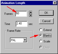
Enter an animation length of 60 frames and click the 'Blanks' radio button. Press OK and examine the timelines in the Keyframer. It might be a good idea to have the Keyframe floating (<Ctrl>+k) so that you can see all the timelines of all the actors at the same time:
The fact that we added 'Blanks' means that none of the timelines for any actor (except the main camera costume) have been extended beyond the first frame. The camera's costume is at (1) above. All the other timelines Costume, position, rotation etc. only exist in frame 1 (see (2) above) . If we were to preview the animation everything would change abruptly in frame 2, with the Model and Light disappearing.
We do not want this so we must extent manually the timelines with the exception of the Model1 Costume timeline. Adding a costume timeline for Model 1 is how we will effect the morphing and I will get back to this shortly. To extend the other timelines take each one in turn and Click on the coloured squares (at (2) above) and drag the timeline out until they all span the full duration of the animation. You should have a display like that below:
At (1) above you can see that the costume timeline for model 1 still only spans the first frame in the animation. Now we come to the point where we will insert the Morph. Click on the Model 1 Costume timeline in frame 30, at point (2) above. A file open dialog will be displayed:
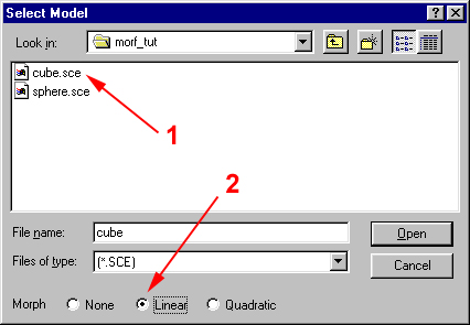
Use this file open dialog to select the second costume for Actor Model 1. Since we started with the sphere we need to load the Cube costume. (at 1 above). To get the actor to change costume from whatever it was wearing previously to this new cubic costume click on the 'Linear' Morph button at the bottom of the Dialog. (at point 2 above). Choosing a Linear Morph, means that actor Model 1 will 'gradually ' change from the SPHERE.MFX model to the CUBE.MFX over the interval between frames 1 and 30. If the morph had not been set there would have been an abrupt change from sphere to cube in frame 2. To complete the animation and morph back from cube to sphere click on the costume time line at frame 60 (at 3 below) and load the sphere again setting a linear morph.
Your completed keyframer settings should resemble that shown above. We will need a black background so double click on the Box at the end of the Sky timeline in frame 60, choose Edit from the Info dialog and use the Edit dialog to set a plain black background for the sky.
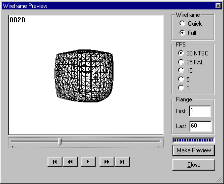
As a final step before rendering the animation use the Frame/Wireframe Preview menu command to make a preview of the effect of morphing:
Use the renderer with your own preferences for size and output format to generate the final animation.
If we look at the results of the animation we will see that the sphere changes to a cube and back to the sphere. It also changes from a yellow colour to a red colour. The images below show the results in frames 1, 10, 20 and 30:
If your browser has the AVI player plug-in you can use the control below to preview the movie. There is one interesting thing in the move. If you look closely at the first couple of frames you will see that some of the facets in the sides of the cubes are very evident. The reason for this is that we did not attempt to smooth the cube; After all a cube is supposed to have flat sides and sharp corners. However as we are morphing it to a sphere it should be near smooth. We can achieve this be loading the model into the Modeller module and setting the 'Smooth' Check Box in the Attributes dialog.
OpenFX is quite clever and decide for itself whether edges should be smoothed out or not. Have a look at the result below. Note also that I have set the whole of the 'Model 1' actor to rotate by adding a Rotation timeline with an Internal Rotation. This just adds a small effect.
In the next tutorial we will look at Quadratic Morphing and under what circumstances you can and you can't use OpenFX's Dissimilar Morphing.