
This strange term describes the process of faceting a curve using the Draw Tool or 3D Plot Tool.
To try this, draw a curve like the one shown below using the DrawTool.

Draw an edge between vertex 6 and vertex 1 to close the curve. Make sure you click exactly on top of vertex 1, otherwise a new vertex will be added and the curve will not be closed.
With the curve in Figure 1 created, have a good look at it in the Camera View. The OpenGL Shaded Camera View will display nothing since the curve must be faceted (filled) first. Note that you can see the wireframe curve if the OpenGL Saded Camera View is turned off.
Create an edge between vertex 2 and vertex 6 as shown below. With the DrawTool enabled, click exactly on vertex 2, then on vertex 6

Once the edge has been created, you should see (lower right hand corner of the status bar) that the number of faces increases by one -- you have created a face! The face in question is composed of vertex 1, vertex 2 and vertex 6. Take a look at these vertices to verify this (that they form a triangle). Now we can proceed to create two more edges to form all the necessary faces. Create edges from vertex 3 to vertex 6 and vertex 4 to vertex 6 as shown in Figure 3.

After these edges have been created, you should see a solid 3D shape displayed in the OpenGL Shaded Camera View.
Now try a more complex outline.
Draw an outline of the letter 'C' as shown in Figure 4.

You should be able to close the curve with the DrawTool alone. The outline is a very rough approximation of the letter 'C'. This is entirely due to some questionable drawing skills! Hopefully you should be able to produce a better C. It does not matter if your outline has more vertices than the one above, you should be able to follow the instructions anyway.
Using the Draw Tool and the strutting technique described to create Figure 3, create an edge between vertex 1 and vertex 3. This will create a face (check for the triangle). Create another edge between vertices 3 and 15. Another face will be created (check again). Then create an edge between vertices 15 and 4. Yet another face will be added. Hopefully you should also see why this technique has been called "strutting". Continue creating edges and faces until you have something like that shown in Figures 5 and 6 below.


The sequence for creating all the vital edges in the case above is :
| Edge | Edge | |
| 3 | to | 15 |
| 15 | to | 4 |
| 4 | to | 14 |
| 14 | to | 5 |
| 5 | to | 13 |
| 13 | to | 6 |
| 6 | to | 12 |
| 12 | to | 7 |
| 12 | to | 8 |
| 8 | to | 11 |
| 11 | to | 9 |
The edge marked in red is important. It represents a change in rhythm. You should be able to see the pattern in standard strutting : a to b, b to c, c to d. However, the marked red edge violates this pattern. This is often necessary to avoid having long thin faces. Note the angle between edges 12 to 11 and 12 to 7 on the left is much greater than 90%. The best choice on the right keeps the angles close to or less than 90%.
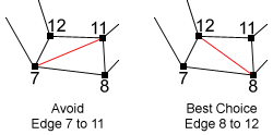
RULE 1: Always avoid long thin faces.
This is not just a matter of style. The Renderer will usually cope with long thin faces, but it will increase the rendering time. Having long thin faces often makes the model more difficult to manipulate. So, although there is no real prohibition against long thin faces, they should be avoided.
While you where faceting your 'C' outline, you may have felt the need to change the rhythm of the strutting to avoid violating rule 1. This should be quite natural. Just keep in your mind the objective of rule 1 and, after a little practice, faceting outlines should become second nature.
If you have successfully created you solid 'C' shape, then you can extrude it into a solid character for a 3D font. You can try applying colors and textures to the model for the 'C'. You could even save it for later use as an actor's costume in an animation.
RULE 2: Never, never have faces on top of each other.
Figure 10 demonstrates what four faces sitting on top of each other looks like.
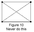
Figure 11 shows a similar arrangement of four faces that is perfectly correct to use. Look carefully to see that none of the four faces is sitting on top of any other one.
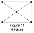
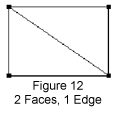
Figure 12 shows how a single edge will create the two faces necessary to facet the rectangular outline of Figure 10.
Rule 2 is not quite a absolute as it sounds. The Renderer does a "depth sort" which should eliminate any problems in the final image, but it is very bad style to create models with faces sitting on top of each other.
Figure 11 actually shows what the rectangular outline would look like if faceted by the Fill to Cursor action. The contrast with Figure 12 should enable you to make some distinction between faces created by strutting and faces created by the Fill to Cursor action. Note that the Fill Outline action would have faceted the outline as in Figure 12.
As mentioned before, both methods of faceting have advantages and disadvantages. The Fill to Cursor action creates an extra vertex which is not strictly necessary for faceting the outline. Therefore, strutting is a more economical method (it does not need an extra vertex). However, having an extra vertex which is a member of all the faces can be an advantage. In the simplest case this can just be an Auto-Filled circle (as described above). It is then possible to grab the center vertex of the solid circle (disk) and pull it up above the circle using the Vertex Selector Tool. This will create a cone similar to an ice-cream cone.
The cone example is just a very basic demonstration of how powerful it is to have 'control' vertices embedded in the model. These vertices can be moved around to dramatically alter the appearance of the model. This technique should be remembered.
Another, not so obvious economic advantage of the structure in Figure 12, is that it has just two faces. The filled structure in Figure 11 (the Auto-Filled one) has four. Of course, the less faces you have the better (less memory is used, renders faster).
Finally, in what is the most advanced example of faceting, holes will be considered.
A brief note should be made about triangular holes. You may have already tried to create the letter 'A', but you may have got stuck on the triangular hole. This appears to be a real problem. If a triangle defines a solid face, how can you have a triangular hole ?
The solution is simple, and like many techniques in animation, a cheat. Create your triangular 'hole' as a normal triangular face. Then select the two vertices at the end of one of the triangle's edges. Subdivide the edge. Now you should have a shape with 4 vertices. Remove the edge that 'crosses' the would-be triangular hole and you will really have a true hole. This is because by Subdividing one of the edges, you changed the 3 sided triangle into a 4 sided quadrilateral. However, the quadrilateral was still solid, so you removed the crucial edge and turned it into an outline.

You should have an outline that looks triangular but it is composed of 4 vertices, so it is not triangular and not a face. If you did not completely understand this explanation then don't worry. After you have had a little more experience it should become clearer. (Just try and create the letter 'A' !)
But once you have the outline (hole and all) how do you turn it into a solid shape ready to be extruded? This is demonstrated by the outline below
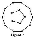
In Figure 7 you can see two circles, one inside the other. For this example suppose the inner circle is a hole. Create the circles for yourself (the outer one has 10 vertices, the inner one has 5). Look carefully at how the edges are added.

Try this technique on your copy of the circles. Once you have done that, adding the edges shown below should be easy.
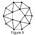
Check that all the faces have been added properly.