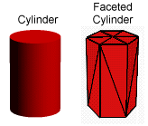
This is a procedure that helps to remove the faceted appearance from the curved surfaces of models.
The diagram below shows a cylinder and a faceted model.

When lighting conditions and surface color are taken into account, that is, it has been shaded, it will look like:

This is because triangles are flat surfaces. At an edge, between two triangles, there may be a change in direction between the planes in which the triangular faces lie. Since it is the angle between these planes and the direction of the light that dictate the shading of a 3D model, the edges of a face are particularly noticeable. If two triangles lie in the same plane, shading them will appear to remove the common edge.
There are many places in an object where there should be visible edges, I will call them creases. A cube would not be a cube if it did not have creases on its edges.
However models have many curved surfaces which we have approximated by triangular faces. Unfortunately an almost unlimited number of minute triangles would be required to get a perfect model for the curved surface.
In essence there are two types of areas on the surface of an object. One is inherently angular and the other is inherently curved.
The faceted method of modeling does a very good job of modeling the angular surface areas, but it is necessary to find a way to make curved surfaces look curved without having to add thousands of minute triangles.
A cylinder (build from a set of triangular faces) poses a very interesting problem. It has a curved side which we would like to look smooth. The top and bottom are flat but the edges between the side and top, and the bottom and side, should remain visible. Therefore there are two flat pieces joined to a curved piece with a crease in between.
This property of the cylinder is quite difficult to model correctly, and it will be reconsidered it later.
There are a couple of methods that are used to make curved surfaces look smooth. They are called Gouraud shading and Phong shading, named after their creators. Both are approximations, Phong shading gives a more realistic look to objects but it takes longer to render. The Renderer uses Phong shading.
Important Note: It is important to realize that no smoothing method smoothes outlines.
Because the eye takes much less note of the edges of an object than abrupt changes in shading on the visible surface, it is possible to get away with only smoothing surfaces.
Look at the diagram below; it shows a cylinder and a smoothed and shaded representation. Note the lack of creases in the curved part of the surface. Note also that the edges have not been made curved!
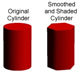
It looks a very much better cylinder than if smoothing had not been applied. This has been achieved without adding any vertices, edges or faces!
The curved edges could be smoothed by adding only a few extra vertices, a lot more would be required if it were necessary to smooth the whole surface by adding more faces!
That's the good news. Unfortunately, with any approximation come a few drawbacks.
The main problem occurs if you try to smooth triangulated surfaces on which there are very large angles between faces that have a common edge. Faces with an angle greater than 90 degrees will look very strange if smoothing is applied.
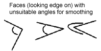
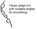
If possible, smoothing should only be applied to faces with angles of 60 degrees or less (to adjacent faces). You must be quite selective in which faces you choose to apply smoothing too.
A few more words need to be said about the problem that was hinted at earlier with regard to the cylinder.
There will be no problem (with angles) in smoothing the curved surface of the cylinder provided 6 or more edges around a circular end were used (12 triangular faces on the curved surface). However it is desired to retain the crease between the top surface and the side, and of course at the bottom as well.
To achieve this smoothing should be applied to the faces on the curved surface only.
For a cylinder such as the one shown below this can be done by selecting all the vertices that make up the cylinder and then setting smoothing to OFF. Then, by using the Selector (in a window which show the circular section), the vertices at the center of the top and bottom surfaces are selected. Finally by clicking on the Select Swap icon the appropriate vertices are selected. Smoothing is activated for faces in the Designer's Attributes dialog.
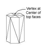
If the above procedure is followed, the Renderer carefully leaves the crease alone.
If you just selected all the vertices in the cylinder and set smoothing On you would just get a blur where the crease was supposed to be, and probably several dark patches elsewhere in the image.
Sometimes it is just not possible to get all the creases you want using the approach above. For example if two smoothed surfaces are joined together. In these cases, don't join the faces from the two surfaces but just put them very close together. You won't see the gap (between the surface patches) in the image, if they are close enough together.
Common
Edge
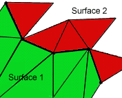
Use
2 Edges (one for each surface)
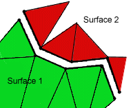
There is one other situation that should be avoided when building smooth surfaces on objects.
Each edge should be common to two faces at most.
Avoid designs that involve structures such as that shown below.
Edge
Common to more than 2 Faces
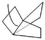
In that example an edge is common to three faces and the Phong smoothing algorithm won't know which ones make up a smooth surface. This type of situation arises mainly if there are "Internal Faces" in a model. Internal faces are usually unnecessary, unless you have some faces made of glass and you want to see into the inside of the model. If this is the case then don't join the internal surfaces to the outer surfaces. Use the trick described earlier for keeping creases in a model.