Next | Prev | Up | Top | Contents | Index
Cabling the Serial Ports
This section describes the cables typically used to connect the computer to terminals and modems. The serial ports are designed to connect directly to Data Communications Equipment (DCE) devices such as modems through a serial cable. Each wire on this cable connects the same pin of the computer socket to the device, that is, it has a pin-to-pin correspondence. Connecting to Data Terminal Equipment (DTE) devices such as terminals requires a different cable arrangement: a null modem cable. A null modem cable has input and output signals swapped between the two connectors.
DB-9 Serial Connector Cabling
Table 1-5 lists the pin definitions for an example of a 9-pin (DB-9) null modem cable, as shown in Figure 1-1. Connect pins that are shown separated by commas in the Terminal column together with a wire or jumper at that end of the cable. Then connect these joined pins to the pin shown in the 9-pin column at the 9-pin end of the cable.

Figure 1-1 : DB-9 Connector
Pin Definitions for a Null Modem Cable
| 9-Pin | Signal | Terminal | Signal |
| 2 | Transmit Data | 3 | Receive Data |
| 3 | Receive Data | 2 | Transmit Data |
| 4 | Request To Send | 5 | Clear To Send |
| 5 | Clear To Send | 4 | Request To Send |
| 7 | Signal Ground | 7 | Signal Ground |
| 8 | Data Carrier Detect | 6,8 | Data Set Ready and Data Carrier Detect |
| 9 | Data Terminal Ready | 20 | Data Terminal Ready |
Most terminals do not require the various handshaking lines such as Clear To Send or Data Set Ready and work with a three-wire null modem cable. To make one of these, you simply need to swap the signals for pins 2 and 3, and you need to connect pin 7 of the computer to pin 7 of the terminal. Table 1-6 lists the pin definitions for a three-wire null modem cable.
Pin Definitions for a Three-wire Null Modem Terminal Cable
| Computer | Signal | Terminal | Signal |
| 2 | Transmit Data | 3 | Receive Data |
| 3 | Receive Data | 2 | Transmit Data |
| 7 | Signal Ground | 7 | Signal Ground |
Note that the pinout of these DB-9 connectors is different from that of the DIN connectors that may be next to them. These DIN connectors also have different pinouts from the mini-DIN8 connectors used on some systems and documented in "Mini-DIN8 Serial Connector Cabling." The DB-9 and DIN connectors are connected to the same internal port hardware.
Caution: Do not use a cable designed for an IBM PC/AT(TM) compatible 9-pin connector. It does not work correctly with your Silicon Graphics workstation.
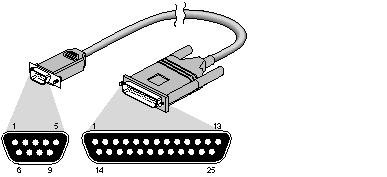
For modem devices that use RTS/CTS hardware flow control, the following pinout allows "full flow control." This cable is required to implement /dev/ttyf* devices. This cable also supports /dev/ttym* devices. (When using ttym devices, ensure that the connected device does not require flow control signals.) Figure 1-2 shows the DB-9 to DB-25 RTS/CTS cable and Table 1-7 lists the correct pin-out for hardware flow control devices.

Figure 1-2 : DB-9 to DB-25 RTS/CTS Modem Control Cable
Pin Definitions for a DB-9 to DB-25 RTS/CTS Modem Control Cable
| DB-9-Male | Signal | DB-25-Male | Signal |
| 1 | not used | 1 | not used |
| 2 | Transmit Data | 2 | Transmit Data |
| 3 | Receive Data | 3 | Receive Data |
| 4 | Request to Send* | 4 | Request to Send* |
| 5 | Clear to Send* | 5 | Clear to Send |
| 6 | not used | 6 | not used |
| 7 | Signal Ground | 7 | Signal Ground |
| 8 | Data Carrier Detect | 8 | Data Carrier Detect |
| 9 | Data Terminal Ready | 20 | Data Terminal Ready |
* RTS and CTS are ignored (optional) if using /dev/ttym* but required if using /dev/ttyf*.
Note: This cable can be used with a null modem adapter for terminals and printers (see Table 1-5); however, it is recommended that you use this cable exclusively for modem connections. The IBM PC/AT to modem cable ("off the shelf cable") does not work properly with your workstation. For additional information see the serial(7) reference page.
Mini-DIN8 Serial Connector Cabling
There are three basic cable configurations for the mini-DIN8 serial ports. See your Owner's Guide to determine if you have a mini-DIN8 port on your workstation or server. Depending on the cables used, some functionality may be sacrificed. Note that the pinout of these mini-DIN8 connectors is different from that of the DIN connectors on larger systems. These larger systems also have DB-9 connectors that are connected to the same internal port hardware.
For most dumb terminals you should use a commercially available cable, Macintosh SE® to ImageWriter1. This cable uses the normal three-wire connection and is used as a /dev/ttyd* device.
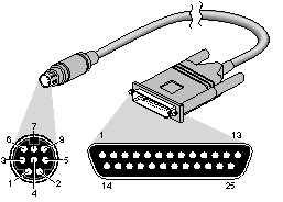
Figure 1-3 shows the mini-DIN8 to DB-25 Serial Terminal Cable and Table 1-8 lists the pin configuration.

Figure 1-3 : Mini-DIN8 to DB-25 Serial Terminal Cable
Pin Definitions for a Mini-DIN8 to DB-25 Serial Terminal Cable
| Mini-DIN8-Male | Signal | DB-25-Male | Signal |
| 1 | not used | 1 | not used |
| 2 | not used | 2 | Transmit Data |
| 3 | Transmit Data | 3 | Receive Data |
| 4 | Signal Ground | 4 | Request to Send |
| 5 | Receive Data | 5 | Clear to Send |
| 6 | not used | 8 | Data Carrier Detect* |
| 7 | Data Carrier Detect* | 20 | Data Terminal Ready |
| 8 | Signal Ground | | |
* /dev/ttym* devices should be used with this cable only if the system must notice when the terminal or printer is powered off.
Note: A Macintosh SE cable has other pins connected but they can be ignored.
For modem devices using RTS/CTS hardware flow control, the following pinout allows "full flow control." This cable is required to implement /dev/ttyf* devices. It also supports /dev/ttym* devices. Table 1-9 shows the pinout:
Pin Definitions for a Mini-DIN8 RTS/CTS Modem Cable
| Mini-DIN8-Male | Signal | DB-25-Male | Signal |
| 1 | Data Terminal Ready | 20 | Data Terminal Ready |
| 2 | Clear to Send* | 5 | Clear to Send* |
| 3 | Transmit Data | 2 | Transmit Data |
| 4 | Signal Ground | 7 | Signal Ground |
| 5 | Receive Data | 3 | Receive Data |
| 6 | Request to Send* | 4 | Request to Send* |
| 7 | Data Carrier Detect | 8 | Data Carrier Detect |
| 8 | Signal Ground | 7 | Signal Ground |
* RTS and CTS are ignored (optional) if using /dev/ttym* but required if using /dev/ttyf*
Note: This cable is available from Silicon Graphics. Contact your sales representative. This cable can be used with a null modem adapter for terminals and printers (see Table 1-5); however, you should use this cable exclusively for modem connections. The commercially available cable that connects a Macintosh SE to a modem does not work properly with Silicon Graphics software.
Next | Prev | Up | Top | Contents | Index


