Note: The second level mapping requires system memory to be reserved for the mapping tables. The current limit on the number of pages that is allocated for map tables is 16 pages and the maximum memory allotted for the map tables is 64 KB. The R4400 provides a 4 KB page size for 16 pages (4 KB * 16 pages= 64 KB). The R8000 provides a 16 KB page size for 4pages (16 KB * 4 pages = 64 KB). Each second-leel map table entry corresponds to 4 KB of physical memory. In addition, each second-level map table entry is 4 bytes. With 64 KB of mapping table, there are a total of 16 K entries translating a maximum of 64 MB of DMA mapping, setting a limit of 64 MB that can be mapped at any time for each VME bus. This does not set any limit on the amount of DMA that can be done by a board during its operation.
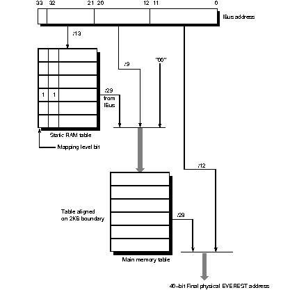
Referring to the top of Figure 13-3, bits 32 and 33 from the IBus address come from the VMECC. These two bits determine a unique VMEbus number for systems with multiple VME buses. Of the remaining 32 bits (31 to 0), 12 are reserved for an offset in physical memory, and the other 20 bits are used to select up to 220 or 1 million pages into the main memory table. However, as stated earlier only 64 KB is allocated for map tables.
As shown in Figure 13-3, thirteen bits go to the static RAM table. Recall that two of the thirteen bits are from the VMECC to identify the VMEbus number. The static RAM table then generates a 29-bit identifier into the main memory table. These 29 bits select a table in the main memory table. An additional nine bits select an entry or element within the table. A 00 (two zeros) are appended to form a 40-bit address into the main memory table.
The main memory table then generates 28-bit address which is then appended to the 12-bit offset of the IBus to form the final 40-bit physical address.

Figure 13-3 : I/O Address to System Address Mapping
Each IRQ on each VME bus is assigned an internal interrupt level, and by default all these levels are at the same priority. If multiple interrupts arrive simultaneously within a single bus, for example IRQ 3 and IRQ 4 at once, priority is given to the higher-numbered IRQ.
All VME interrupts are made to go to CPU 0 (unless configured differently with IPL statements). This prevents one interrupt level from preempting the driver handling a different VME interrupt level.