


Improving RISC PC Video
Dave Holden
Improving RiscPC video
Most people will be aware that there are two main types of RiscPC motherboard in circulation; the Series 1 and 2 boards as fitted to the early RiscPC 600s and the Series 3 boards fitted to the later 600s and all other machines up to the present day. The most obvious outward difference between these two is that the Series 3 board has 16 bit sound whereas the Series 1 and 2 boards only have 8 bit sound and require an add-on board if you want to add the improved 16 bit sound, for example, to play music CDs. What most people are not aware of is that the Series 1 and Series 2 boards actually have better video output that the Series 3 board, and this article describes how you can restore this.
There are a couple of other differences, so while we're on the subject I may as well describe them, but first how can you tell which motherboard you actually have?
Motherboard types
The most obvious place to look would be the Product Code as that should be able to be linked to the motherboard model. That might have been true once, but unless your machine is absolutely original, and has never been repaired, it may no longer be the case. When the Strong ARM upgrade appeared it was not uncommon for it not to work on some of the early Series 1 boards, and so many machines were sent off to Granada Electronics to be fixed. Sometimes, with a particularly unstable machine, the 'fix' involved fitting a Series 3 board, so if you have an early RiscPC 600 with a Strong ARM it might have the latest motherboard. Similarly a lot of component swapping and 'cannibalising' went on in schools. I've seen some very strange 'bitza' machines in lots purchased from schools.
To know what motherboard you have look at the rear of the board, just in front of and to the right of the printer socket. You will see the words:
ACORN
COMPUTER
MAIN PCB
and beneath this a number. The number will be one of three -.
- 0197.000 - Series 1.
- 0197.100 - Series 2.
- 1208.000 - Series 3
This text and the number may be partly obscured if you have an NIC fitted.
The two most important difference between the Series 1 and Series 2 boards are that the S1 boards only have the floppy DS0 line connected so they can only address a single floppy drive, and this must have it's drive ID set to zero. Later boards could address two drives (if required) and if only a single drive is fitted it can have its ID set to '0' or '1'. The other difference is that all S2 boards have modern low profile SIMM sockets whereas most of the S1 boards didn't. This can be a problem, as many SIMMs with chips on both sides, in particular most 32 Mb ones, have the chips very close to the edge of the PCB which means they can't be fitted into the sockets on the S1 boards so you have the fit the rarer, and hence more expensive, 'high clearance' type. Luckily this problem has now largely disappeared as almost all 64Mb EDO SIMMs do have adequate clearance or are single sided.
Series 3 board changes
When the S3 board was introduced there were several changes. Firstly 16 bit sound was fitted, so you could plug a CD directly in to the motherboard. Secondly it was designed from the outset to work with faster processors and with more RAM (32 Mb SIMMs were now common) and no longer required the removal of the infamous C32 if you wanted to fit a StrongARM and lots of RAM. However, there was one change which was retrograde; the video bandwidth was reduced.
This was necessary to meet the new emission regulations. The S1 and S2 boards could exceed the later RFI limits which would have made CE certification difficult. Acorn adopted a fairly unrefined solution to this problem - they introduced a simple passive low pass filter into the VIDC RGB output lines. This removes the high frequency RFI, but it also reduces the video bandwidth and hence can cause some loss of definition in high resolution screen modes. At the time this went largely unnoticed. Eight years ago high definition monitors were much more expensive than they are today, and the monitor that most people used, the AKF60, didn't show the difference, and it was only just noticeable on most examples of the Acorn 17" monitor, the AKF85. However, monitor prices have tumbled, and specifications have risen, and the majority of users now have at least a 17" monitor and expect to be able to use a screen resolution of 1280 x 1024 in 256 colours or 1024 x 768 in 32K colours, and with a modern monitor the reduced video bandwidth of the S3 board is significant.
Luckily it's not a major problem to restore full bandwidth. However, there are a few points to bear in mind.
- This modification could cause your machine to exceed RFI emission standards. .
- You will need to poke about with a soldering iron on your motherboard. Anyone moderately competent should be able to carry out this work but if you have any doubts don't do it. Either leave well alone or get someone who does have the necessary skills to carry out the work. If you do decide to do this and make a hash of it it could require expensive remedial work, and if this happens don't blame us.
- You will need to observe normal anti-static precautions. The RiscPC motherboard is not particularly static sensitive (though the Strong ARM processor is) but do take care.
What you need to do.
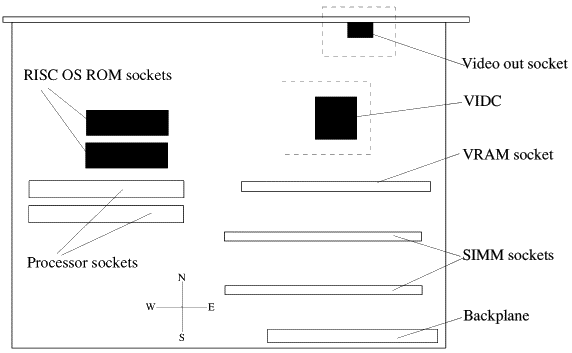
The modifications carried out by Acorn consisted of a small capacitor between each of the R, G and B lines and earth near to the VIDC chip and an inductor in series with each line close to the video output socket. The following illustration shows a RiscPC motherboard with the main components identified. The two areas enclosed by dotted lines are then shown enlarged and in more detail later.
The first operation is to get access to the motherboard. Ideally you should completely remove it, but it's not necessary. You will have to strip the computer to it's base 'tray' and remove the backplane and processor(s). You will probably find it advantageous to remove the VRAM. You may prefer to leave the motherboard in the tray as it keeps it firmly held, and you may also find it useful to leave the power supply in place as it makes a handy rest for your wrist to help steady the soldering iron (if you're right handed).
Before you actually start work make sure that you have clear access - you may find it easier with the power supply moved out of the way.
Removing the capacitors
First you have to remove the three capacitors. The area around the VIDC chip is shown below.
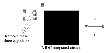
You should be able to identify the three capacitors close to the NW corner of the VIDC chip. To further identify them you will see that just to their right, between them and the VIDC, is the legend 'IC29'.
These are small surface mount devices, about 4mm x 2mm. The 'proper' tool for the job is a surface mount component remover, but you can do it with a conventional soldering iron and a bit of care.
The best tip is a flat wedge, rather like a fat screwdriver blade. If you don't have one of these then you can make one by filing an old bit to shape. It needs to be wide enough to span both ends of the component (about 5mm) and thick enough to conduct the heat, say, about 1.5mm. Place the iron tip square onto the component, making sure it's touching both ends, and, when you see that the solder has melted, you will find that you can probably remove it and the component will 'stick' to the tip of the iron. Sometimes a small sideways movement will help to 'unstick' the component from the board.
Beware of overheating or you may 'peel' the PCB tracks.
Dealing with the inductors
That was the easy part, now you have to turn you attention to the three inductors. These are just in front of the video socket, and are rather more difficult to deal with. As they are in series with the R G B lines the 'proper' way is to remove them and replace them with three small pieces of wire. However, because of their proximity to the socket this is rather awkward as it's almost impossible to get access to the rear of the inductors with a soldering iron.
The illustration below shows the location of the inductors. These are normally light brown in colour, about 4mm long, 3mm wide and 2mm high.
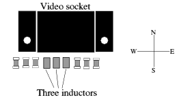
One solution is to use side cutters to break up the inductors so that you can unsolder the residual bits and then fit short pieces of wire in their place. The problem with this is that if you apply too much force you can easily damage the PCB tracks or pull one or both of the attachment pads completely off the board.
A simpler solution is to leave the inductors in place and 'bridge' them with short pieces of wire. This is possible because although you can't get at the rear of the inductors you can easily get at the socket itself, so you can fit a bridging wire between the solder pad at the front of the inductor and the respective video socket connector. Luckily the three inductors are connected to the three left hand ('E') connectors on the video socket, and these are easy to get to. You will see the vertical flat wires which form part of the video socket, and to bridge the inductors you will need three pieces of tinned copper wire (resistor 'tails' are ideal for this) shaped as shown.

The upper vertical section is soldered to the video socket connector, the horizontal part then bridges the inductor and the bottom of the lower vertical part is soldered to the front ('S') PCB pad of the respective inductor. I would advise you to clip a heat sink onto the wire before you make the second joint as otherwise, with such a short piece of wire, enough heat will probably feed back into the first joint to melt it and the wire will come away stuck on the tip of the iron.
You may find it easiest (I do) to just make the first bend on the wire, attach it to the socket, and then snip it off to length and make the second bend with a pair of very thin nosed pliers. If you are right handed then start with the left hand ('W') side. If you are left handed start with the right hand ('E') side. If you work the other way about then you will find that the link already done will be in the way when you try to do the next one.
Whichever method you use you will need a miniature soldering iron and a steady hand, and I would also advise the use of a magnifier.
And finally...
You will now need to re-assemble the computer, offer up a short prayer to the Gods of RISC OS, switch on and hope it's all going to be OK. If you have a good quality monitor you should notice improved sharpness in the picture.
Unless you are in a hurry you may find it best to check that all is well after completing the first stage (removing the capacitors). However, to restore full video bandwidth you will need to complete both stages.
Dave Holden