This tutorial describes how to load, view and use an existing Geometra project, how to set up a Geometra project from scratch, create a simple and a more complex model using Geometra.
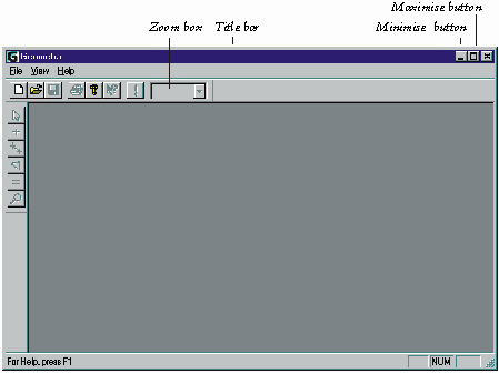
Start the Geometra program, either by double clicking on the Geometra icon on your desktop (if you chose this option on installation), by clicking on the Geometra icon on the Windows Start bar or by finding Geometra.exe with the Windows Explorer program and double clicking on the Geometra icon there. An empty Geometra workspace as shown in Figure 3 will now be presented.

Figure 3: Empty Geometra Workspace
As Geometra works better when it has maximum screen real-estate available it is useful to maximise the Geometra window either by double clicking on the title bar or by clicking on the window maximisation box of the Geometra window.
To open the example file book.gpf Select the File pull down menu and choose the Open entry on that menu.
Select the Tutorial subdirectory of the main Geometra installation directory and then select the box subdirectory. Now select the Geometra project book.gpf and Geometra will load the images and data used in this project.
To tidy the workspace a little select the Window pull down menu and choose Tile. To make the images fit in the windows use the zoom box (Figure 3) and choose "Fit all".
The screen should now look something like Figure 4.
Figure 4: after opening and window layout of box3.gpf
The six images displayed are the six images that were used in this project to construct a model of a book. In order to see the 3-D model of the book select the View menu and choose 3D Viewer. The screen should now look similar to Figure 5.
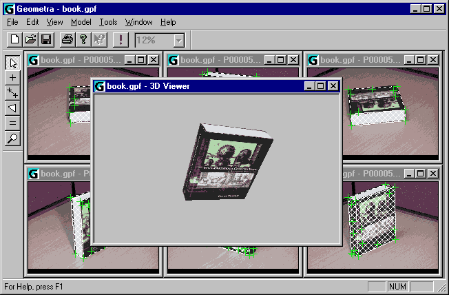
Figure 5: 3-D rendering of Geometra box model
With the 3-D Viewer window active it is now possible to manipulate the 3-D model. The [Page Up] and [Page Down] keys zoom in and out. The four cursor keys and the [Home] and [End] keys allow for rotation along various axes.
Rotation can also be performed using the mouse by making sure the cursor is within the 3-D Viewer window, holding down the left mouse button and dragging with the mouse. A little experimentation will soon make it clear how mouse movement relates to rotation.
It is possible to maximise the 3-D Viewer window to occupy the whole of the Geometra workspace using the 3-D View window's maximise button. Figure 6 shows what the 3-D viewer window looks like when it has been maximised and the model of the book has been moved around a little.
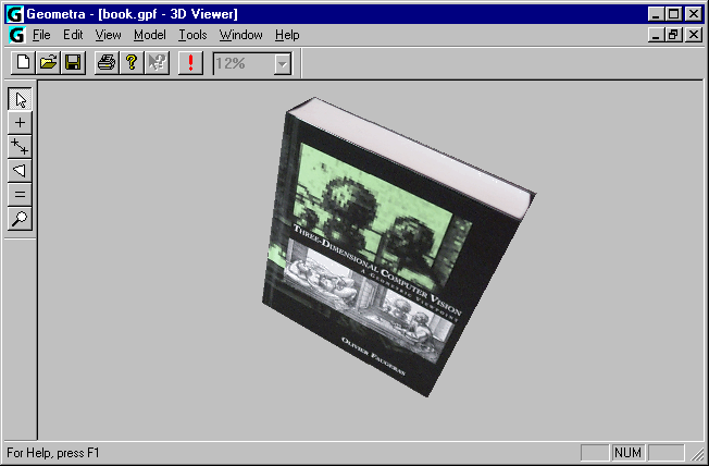
Figure 6: Maximised 3-D Viewer window
It is also possible to choose different rendering options for the viewer to see the model as, for example, a wire frame rendering. To do this select the Tools menu and then the Options entry. A tabbed window appears. Select the 3-D Viewer tab. Uncheck the Show Polygons and Texture Mapping boxes but make sure the Show Lines box is checked as shown in Figure 7 and then click on the OK button.

Figure 7: 3-D Viewer properties
The 3-D Viewer window should now update to show a wire-frame representation of the lines in the model as shown in Figure 8.
Other options are also possible. E.g. checking the Show Polygons box but not the Texture mapping box will result in the box being rendered filled in but only in uniform grey rather than with photo textures.
It is also possible to measure the lines which delineate the book, and to obtain the co-ordinates of the vertex points. In order to do this either close or minimise the 3-D Viewer Window. Then maximise one of the view windows to the full Geometra workspace, e.g. the p0000540.jpg window as shown in Figure 9. Choose the To Fit option for this window using the zoom box on the top toolbar.
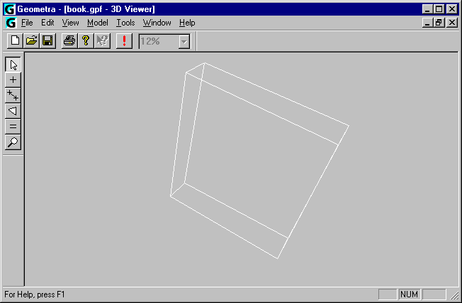
Figure 8: Wire-frame rendering of book model
Make sure that the pick tool is the currently active tool. You can tell which is the currently active tool by looking at the toolbar to the left of the Geometra workspace. The pick tool is the top tool of the 6 on the toolbar (an arrow) and it is shown selected in Figure 9. If not, select it by clicking on it.
When 3-D models are constructed from separate pictures scale is lost. Fortunately scale can be easily reinstated by entering one known element in a model, e.g. the length of a line-segment of know length.
The height of the book is known to be 236 mm. In order to set this, using the pick-tool, click close to the centre of the lines along the vertical book edges, e.g. the left one in Figure 9. The line will change colour (to a red and white dashed pattern) to indicate it has been selected. Next select the Set scale entry on the Model pull-down menu and enter 236 in the dialog box which pops up and click on the OK button.
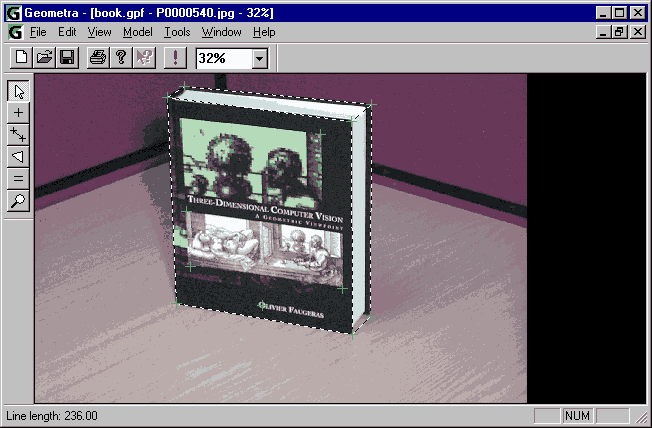
Figure 9: Measurement of book height
Measurements can now be very simply obtained by hovering the pick tool over either a line segment (shown dotted on screen) or a vertex point (green crosses). Measurements will be displayed at the left of the status bar at the bottom of the workspace. The length measurement shown was obtained by hovering the cursor over the line at the left hand side of the book as shown in Figure 9.
All lengths of lines in the current image can also be shown at the same time (page *, Setting display options - image windows). To toggle this option on/off press the D key. The resulting image view of the book is shown in Figure 10.
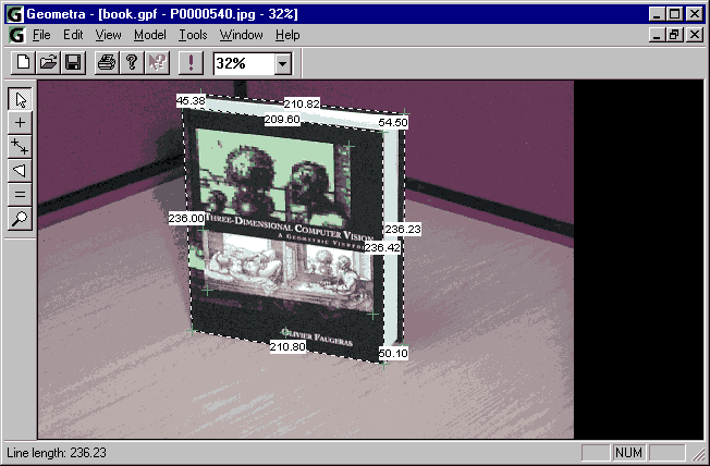
Figure 10: View of book with dimensions shown
In order to close the project select the File menu and then the Close entry. If prompted whether to save changes (because of accidental changes to the Geometra project) select No.
There other example files you can load and view in a similar fashion. In the samples subdirectory you will find the arches, psion and face subdirectories which in turn contain the model files arches.gpf, face.gpf and psion.gpf renderings of which are shown in Figure 11, Figure 12 and Figure 13.

Figure 11: Rendering of arches.gpf
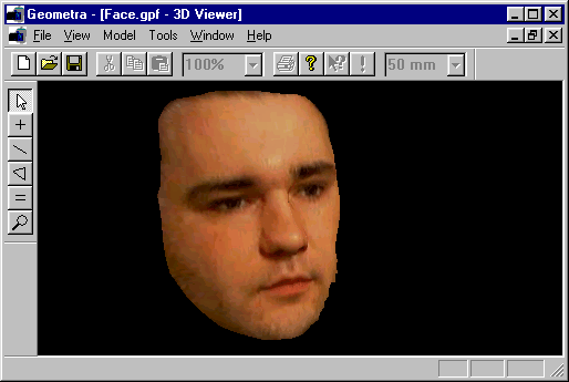
Figure 12: Rendering of face.gpf

Figure 13: Rendering of psion.gpf
As a first Geometra model construction exercise a simple model will be made of the building known as "F4", the building where Geometra was developed.
Constructing a model with Geometra is process consisting of several basic steps.
When these steps have been completed to satisfaction it is possible to view the model, export it in various formats and/or make measurements.
In order to start modelling a view of building F4 a new Geometra project will have to be started and some images will have to be added to this project. If Geometra is already started close any project that might be open, otherwise just start up Geometra to obtain an empty workspace.
To start this new project select the File pull down menu and choose the New entry on that menu. Select the Tutorial subdirectory of the main Geometra installation directory and then select the F4 subdirectory. The Add Images dialog should now look similar to Figure 14.

Figure 14: Add Images dialog
Both of these image will have to be selected into this project. To get both at the same time just select building1.jpg and building2.jpg in the usual windows fashion, e.g. hold down the [Control] key and click on first building1.jpg and then building2.jpg. Then click on the Open button and Geometra will proceed to load the images.
Arrange the two image windows in the workspace so that they are both visible in the workspace, either by manual placing and sizing of the windows. Or by using the Tile entry on the Window menu as previously. In either case make the images fit the whole window by using the To Fit zoom box entry on each of the two windows individually or the Fit All zoom box entry to fit both images simultaneously. The workspace should now look something like the one shown in Figure 15 (optimised for this printed documentation).
Figure 15: Two images of F4
The same physical point on the building will appear at different points in the two (in this case) images. In order to avoid confusion two different terms are be used to distinguish these kinds of points.
The physical points are referred to as world-points. World points are unique as a point in space cannot be in more than one place at the same time.
Points in images are referred to as image-points. Image-points are not unique as a single world-point observed in a number of different images (in this case two) will appear in different image-points in each of these images.
Image-points which belong together (because they correspond to the same world point) are linked together by a reference.
So having loaded in these two images the next step is now to reference corresponding image-points in these two images to each other. This is done using the reference tool (see list of tools in Figure 15). The first image-points referenced will be those corresponding to the world-point which is the top foremost corner of the building as shown in Figure 15.
The reference tool can be used in two ways:
It is the first mode of use which is the most common and it is also the one we will use now.
Having made sure the reference tool is selected. Left click on the foremost corner image-point first in one image and then in the other. Both image-points will now appear marked by a yellow cross. To indicate that this reference is now complete right click (with the cursor anywhere over either image) and the crosses over the image points will go green indicating that these image points have been referenced.
To verify that both of these image-points have been referenced (i.e. belong to the same world-point) we can turn on point number display. To do this select the Tools menu and then the Options entry. The tabbed options window appears. If not already active select the Edit tab. Make sure the Show numbers entry is checked as in Figure 16.

Figure 16: Edit options
Alternatively number display can be toggled on and off by pressing the N key whilst editing, i.e. with the cursor over one of the two images.
One reference is not enough to be able to reconstruct a 3-D model though so a few more will have to be entered using the reference tool: clicking on an image point in one image (yellow cross appears), left clicking on the corresponding image point in the other image (second yellow cross appears) and then right clicking to complete the reference (both crosses turn green).
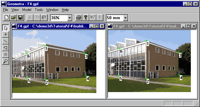
Figure 17: Six references entered
Suggested references are shown (with point numbers displayed) in Figure 17.
In order to make a model some structure needs to be attached to world points. The simplest example of such structure is lines.
Fist check that line are set to display while in edit mode by selecting the Tools menu and then the Options entry. The tabbed options window appears. If not already active select the Edit tab. Make sure the Show lines entry is checked as in Figure 16. Again there is a keyboard shortcut and line display can be toggled on and off by pressing the L key whilst editing, i.e. with the cursor over one of the two images.
In order to insert some lines start by selecting the line tool (Figure 15). Start by drawing four lines delineating the rectangle with corner points 1,2,5 and 6. With the line tool active (an appropriate cursor will appear) click on or near the image-point labelled 1 in the first image. Next click on or near the image-point labelled two, then 5, then 6... To stop drawing this continuous series of lines right click.
The Geometra workspace should now look something like Figure 18 with the rectangle (sequence of four lines) displayed in both images, not only the one in which it was drawn. This is because, through the referencing, these points are known to correspond to the same world points.
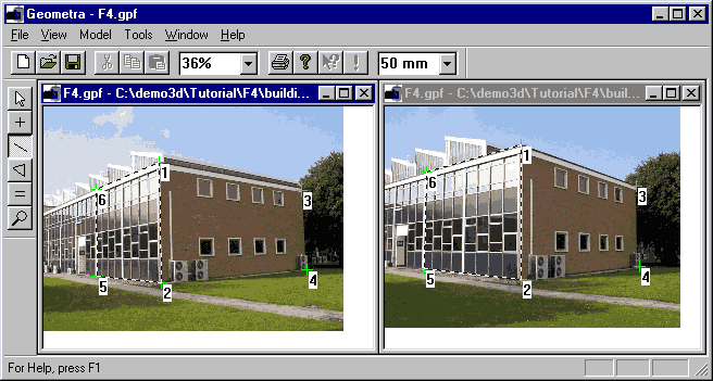
Figure 18: One rectangle entered
Now the second rectangle can be entered as well, this time doing it as separate lines: in either image click on image-point 3, click on image-point 4 and then right click. Do the same between 1 and 3 and then 2 and 4. There will now be a second rectangle defined as shown in Figure 19.
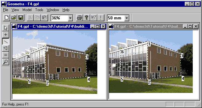
Figure 19: Two rectangles, seven lines entered
Before anything 3-D can be done with these lines (display them in the 3-D viewer, export a model, etc...) Geometra must calculate the 3-D positions of the world-points from the entered 2-D positions of the image-points and the references tying them together. In order to do this choose the Calculate entry on the Model menu.
Once the calculation has finished we can view the wire-frame model in the internal Geometra 3-D viewer. First, as before with the box model make sure that line display is set on for the 3-D viewer (Figure 7). When a 3-D viewer window is actually displayed and has focus then line display can also be toggled using the L key.
Pull up a 3-D viewer window and the Geometra workspace should look something like Figure 20.
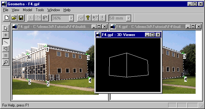
Figure 20: Wire-frame view of F4 model
The wire-frame can be moved around using either cursor keys or mouse as before.
To make for a more interesting model it is desirable to add some textured polygons as well. In this particular example the texture will be extracted from the leftmost image as shown in the figures. Move the current 3-D viewer window out of the way as shown in Figure 21.
The process for entering polygons is very similar to the process for entering lines. Start by selecting the polygon tool (Figure 15). The cursor will change to the polygon tool cursor.
Make sure that polygon display in edit mode is switched on by checking under the Edit tab of the Geometra option dialog (Figure 16) and making sure that the Show polygons box is checked.
As a first polygon enter the triangle between points 1,2 and 6. Click on point one, left click on point two and left click on point 6 then right-click. A shaded triangle should now appear superimposed on the image and the 3-D viewer window should update to look like Figure 21.
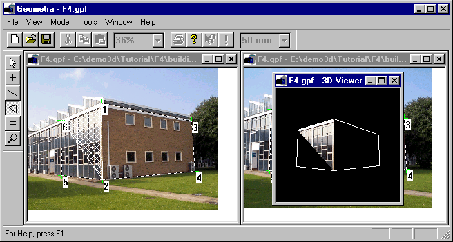
Figure 21: One triangular polygon
The triangle between 2,5 and 6 can be added in similar fashion. With the polygon tool still selected click on point 2, left click on point 5 and left click on point 6 then right-click. Another shaded triangle will appear in the image window and the 3-D viewer will again automatically update.
It is also possible to add polygons with four vertices. The difference with triangular polygons is simply that it is no longer necessary to complete the operation by right clicking.
Using this feature the polygon spanned by 1,2,4,3 can be added in one go: With the polygon tool still selected click on point 1, left click on point 2 and left click on point 4 then left click on point 3. A shaded rectangle will appear in the image and the 3-D viewer window will again update to look like Figure 22.
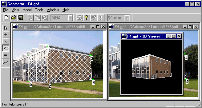
Figure 22: Two sides of F4
To make the model look more natural switch off the 3-D Viewer wire-frame display again using either the Geometra properties dialog or by pressing the L key while the 3-D Viewer window has the focus. Make the 3-D Viewer window a little larger and manipulate the model a little, look at it from a perspective a little different from the ones in the two original pictures.
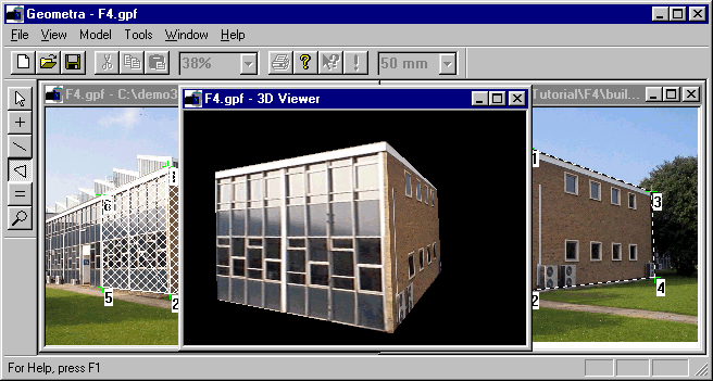
Figure 23: F4 from a different perspective
At this point it might be a good idea to save a version of the project. To do this select the Save As entry on the File menu. The selected directory should still be F4. Just enter f4.gpf (or any other name you wish) as the file name.
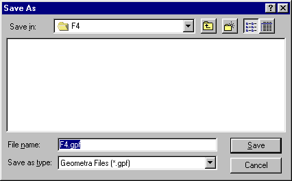
Figure 24: Save As dialog
In case mistakes are made when entering, points, lines or polygons it is of course also possible to edit and/or delete them. Or select Undo from the Edit menu (keyboard shortcut [Control]-Z) to undo the last actions or actions performed. More information on undo functionality can be found on page * in the section titled Undoing mistakes.
Move the 3-D Viewer window out of the way again as before. To move a point make the pick tool active (if it isn't already) by clicking on the pick tool button (Figure 15). In order to try out moving a point we will (temporarily) misplace image-point 4. This can be done easily by positioning the pick tool over image-point 4, clicking the left mouse button and holding it down, dragging until the desired new position for point 4 is reached and then releasing the left mouse button. The result of a move of point 4 in the first image is shown in Figure 25.
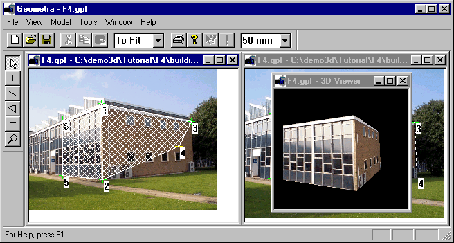
Figure 25: Misplaced point
You might have noticed that the 3-D Viewer didn't update as a result of this move. Because the calculations can be a little time-consuming actual calculation of 3-D positions is only performed on request, when invoked by the Model, Calculate menu entries. Doing so now would give unpredictable results because the two image-points referenced as 4 no longer properly correspond to a single world point! If you try it you might get something like Figure 26, with a warning depending on exactly where you misplaced the point.
If you did try this then move point 4 back to it's proper position again using the pick tool (or use undo) and Select the Calculate entry on the Model menu. If you misplaced point 4 really badly before then it might be that this doesn't make the model bounce back into shape immediately. In that case select the Reset Calculation entry on the Model menu and then the Calculate entry on the Model menu.
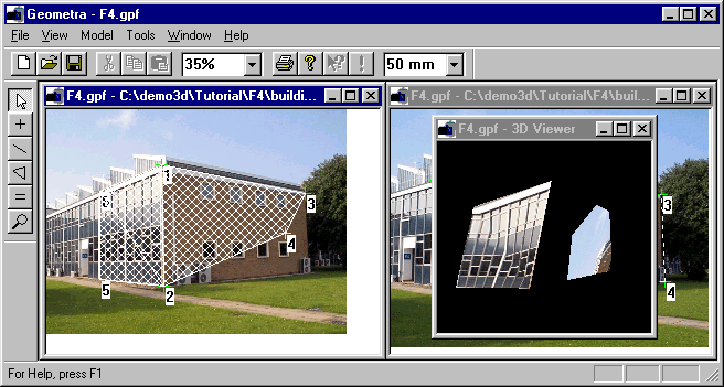
Figure 26: Reference 4 is wrong
If that still doesn't work then close the Geometra project (File menu, Close entry), re-open the file you saved earlier (File menu, Open entry) and re-arrange windows and viewing options as before. In general, as with all software, it is advisable to save your work often.
Polygons cannot be moved by themselves but they can be moved by moving the image points to which they are attached, as happened in the previous example. It is also possible to delete undesired polygons. In order to do this a polygon should first be selected. Make sure the pick tool is the currently selected tool and click approximately in the centre of the polygon spanned by 2,5 and 6. The polygon should now turn red as shown in Figure 27.
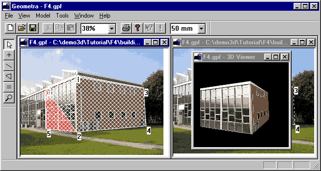
Figure 27: Selected polygon
Another polygon can be selected by clicking inside another polygon or a selected polygon can be de-selected by clicking within the image but outside of any polygon, e.g. in the blue sky. For now make sure the polygon is selected as in Figure 27.
The polygon can now be very simply deleted by pressing the Delete key (or selecting Delete on the Edit menu). The 3-D viewer window should also update to reflect the deletion of the polygon as in Figure 28.
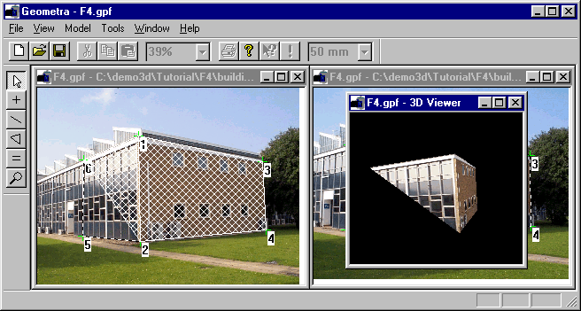
Figure 28: Model with a polygon deleted
As the polygon should actually be there it is best to enter it again. Either use undo ([Control]-Z) or select the polygon tool then click on point 2, left click on point 5, click on point 6 and right click to finish the polygon (as this is a triangle and not a rectangle). The model should now return to a state similar to Figure 23.
In order to improve the accuracy of the model it can be desirable to zoom in on the image points in order to be able to position them with greater accuracy. As an example we zoom in on the image-point at the lower right corner of the rectangular polygon (number 4). This could be done by selecting a zoom factor in the zoom box then using the scroll bars to position the displayed image portion to be in the window in this instance use the zoom tool.
First turn off polygon display by un-checking the Display polygons box under the Edit tab of the Geometra options dialog or just by pressing P with the cursor over an image window.
Make the zoom tool active by clicking on the zoom tool button (Figure 15). To zoom in on the area at the lower right hand corner of the building position the zoom tool to the top left of the corner of the frame of the window at the bottom right of the building, click and hold down the mouse button. Drag the rectangle over the area desired, i.e. to just below and to the right of point 4 and then release the left mouse button. The zoomed view should look similar to the one in Figure 29.
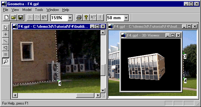
Figure 29: Zoom-in on corner
If the zoom hasn't gone quite as desired it is easy to return the image to full size (use the F keyboard shortcut to fit the image to the window) and try again using the zoom tool.
With the zoom done it is now possible to position point 4 in this image very accurately. Activate the pick tool and accurately position point 4 over the lower right corner of the wall. As this is actually obscured by the fan-unit accurate positioning is aided by using the two lines (lining them up with the horizontal and vertical edges of the wall). With the point still selected it is also possible to fine tune it's position using the [Left],[Right],[Up] and [Down] cursor keys without using the mouse.
To really increase the accuracy of the model the position of all six image points in both of the images will have to be refined like this. There are several ways this could be done. Use the scroll bars to scroll the view of the image left to point 2, reposition that, then 5... Or just use the zoom box or F key to return the window to a To Fit state and use the zoom tool to zoom in on individual points. In any case remember to adjust the points in both images.
Having refined all the point positions Model, Calculate again is again in order to have the model re-calculated. If the 3-D Viewer window was closed while fine-tuning the image-points then open a new one just to verify the model is still present and correct. If so, this is a good time to save the project again. From the File menu select Save.
Accuracy can be further enhanced by adding some more referenced image-point pairs. Even if these don't yield a more detailed shape in terms of the number of polygons in the model they will allow Geometra to more accurately estimate 3-D shape from the referenced image-point sets. In fact the number of references used in this tutorial example (6) is very low. We would recommend 12 as least.
Add in a few now. Using the reference tool as before. Perhaps with the zoom for both images already set to 100% or higher so you can put the references in proper position right away. Also note that there is a way of saving mouse-clicks. When entering a reference it is possible (with the reference tool active) to click on an image-point in the first image, then click on the corresponding image-point in the right image. The reference can now be finished by right-clicking or simply by starting a new one by clicking an image-point in the first image again. This will automatically finish the previous reference. Geometra is aware of the fact that how ever many images you may be referencing, a reference always has to be between points in different images so the fact that you are again clicking in an image where you started a previous reference must mean that you finished it and you are starting a new one.
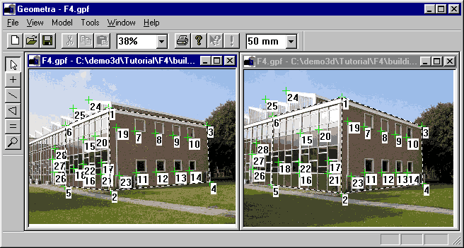
Figure 30: A few more references added to the project
Figure 30 shows the workspace after a few more references have been added in.
Try opening another 3-D Viewer window and examining the model one more time. Remember the keyboard shortcuts you can use in the 3-D Viewer: L toggles the display of lines, P toggles the display of polygons and T toggles the display of texture (but only if polygon display is actually on).
Assuming the operations to have been successful save the file again.
Having successfully made a model we can now export it in VRML format. Before doing this check the VRML export options (Tools, Options, under the VRML tab). The relevant dialog window is shown in Figure 31.
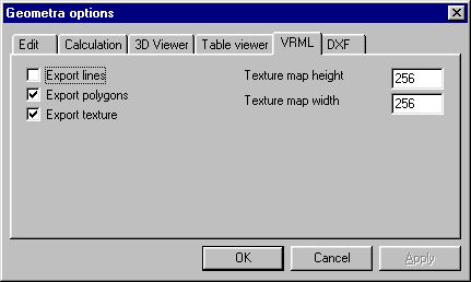
Figure 31: VRML export options
The three check boxes refer to which model elements will be exported and have much the meaning as in the internal Geometra 3-D Viewer, so the most common settings (as shown in the figure) will be to export polygons with textures and not lines.
The texture map height and width boxes refer to the dimensions of the texture bitmaps which will be exported along with each textured polygon. It obviously doesn't make too much sense to make this dimension larger than the image size of the input images. Equally an 8x8 texture will not look very good at any significant magnification. Choosing a reasonable dimension as shown in the figure is best. As JPEG compression is used on the textures choosing a slightly larger texture map will not be penalised by much larger file size.
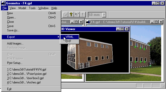
Figure 32: VRML export
So select the Export entry from the File menu (as in Figure 32) and select the VRML sub-option as also shown.
The Export VRML dialog box (Figure 33) will now appear. Create a subdirectory of the F4 directory and call it vrml. This can be done by selecting the F4 directory (if not already selected) and then using the new folder button (the one with the cursor over it in Figure 33).
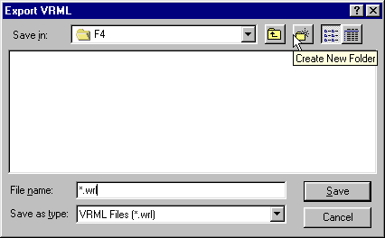
Figure 33: VRML file export dialog
Having done this enter the newly created vrml subdirectory (by double clicking on the vrml folder icon) and then enter the desired file name in the File name text box, e.g. f4.wrl and click on the save button.
The files which make up the VRML model (Figure 34) should now be saved ready for use in whatever web-publishing tool or VRML authoring tool may be desired.
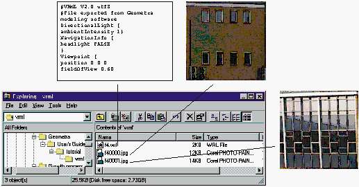
Figure 34: VRML files