
This chapter contains information on some of the basic procedures involved in building and working with Geometra models as well listing details for options and settings of Geometra.
This section lists and described the basic component procedures and actions which together constitute working on a Geometra project.
To start a new project select the File pull down menu and choose the New entry on that menu. An Add Images dialog similar to the one shown in Figure 36 will appear. If necessary navigate the directory structure to reach the directory in which your image files are located.

Figure 36: Add Images dialog
Having reached the directory which contains the image files select all the image files you want to use in this Geometra project using the usual Windows means for selecting multiple files. To select a contiguous group of files click on the first file name, hold down [Shift] and click on the last file name. To select a random selection of files click on the first file name, hold down [Control] and click on all other individual files you want to select before releasing [Control].
Then click on the Open button in the dialog box and Geometra will proceed to load the images into the Geometra workspace.
It is possible to add new images to an existing Geometra project. With the project to which images are to be added open in the Geometra workspace select the File pull down menu and choose the Add Images entry on that menu. The Add Images dialog (similar to the one shown in Figure 36) will appear. If necessary navigate the directory structure to reach the directory in which your image files are located. Having reached the directory which contains the image files select all the image files you want to add to this Geometra project using the usual Windows means for selecting multiple files. To select a contiguous group of files click on the first file name, hold down [Shift] and click on the last file name. To select a random selection of files click on the first file name, hold down [Control] and click on all other individual files you want to select before releasing [Control].
Then click on the Open button in the dialog box and Geometra will proceed to load the images into the Geometra workspace, adding them to the project which was already open.
To remove an image (and all image points within it) from a project click on that image's close button (the button at the very right of the image window's title bar, next to the minimise and maximise buttons). The Remove Image dialog will appear. Click OK to remove the image.
To replace an image make sure that the image window it is represented in has focus (it's title bar is highlighted) then select Replace Image from the File menu. The Replace Image dialog appears. Select the image file you wish to replace the current image from and click on Open. The current image will be replaced.
There can be several reasons for replacing images in Geometra. For instance, images might have been contrast adjusted or histogram equalised in external software and then saved under a name which is different from the original file. As the geometry of these images will of course be totally the same as those of the original image they can be substituted directly for these original images in the project.
A more advanced technique is to place small markers (e.g. stickers) on the object to be modelled. These markers are easy to find and click on to insert image-points thus making it easier to make a model. However they will also appear in the texture of the model produced and this is less desirable. Fortunately such markers would be placed in areas of uniform texture (e.g. plain coloured surfaces) where there are no other features to place image points on. In such areas it is very easy to photo-edit the markers away using (third party) photo-editing software to obscure the markers using similar local texture (with copy and paste or a 'clone' tool).
The whole procedure would then be to build the model in Geometra using the images with markers on the object(s) to be modelled. Next remove the markers from the images by photo-editing and save the images under a (slightly) different name. Replace the original images in the Geometra project with the edited ones and export or work with the model as desired.
A project which already has a name can be saved by selecting the File pull-down menu and choosing the Save entry or click on the save button on the top toolbar (the button marked with a floppy disc).
A project which has been saved previously will be automatically saved. If the project has been newly created then the Save As dialog will come up prompting for a file name before the file can be saved.
It is highly recommended to save the Geometra project file in the same directory as the images used in the Geometra project.
The focal lengths stated on digital cameras are usually 35 mm equivalents which Geometra can use directly.
To set the focal length for a new or existing project select Model on the pull-down menu, then the Set entry and Focal Length. In the dialog box enter the appropriate (35 mm equivalent) focal length and click on the OK button. This need only be done once as the focal length will be save (and subsequently loaded) with the Geometra project.
Image-points can be inserted in images using either the point tool or the reference tool. The difference lying in the fact that points inserted with the reference tool are automatically referenced to each other.
To insert a point using the point tool make sure the point tool is active, then click on the desired location in the image where the point should be inserted. As the point inserted is unreferenced it will be marked with a red cross.
To insert a point using the reference tool make sure the reference tool is active and then click on the desired location in the image where the point should be inserted. A yellow cross will appear. For each point which you would like to insert in other images and make part of the same reference click on the appropriate-image location, these points will again be marked with a yellow cross. To finish the reference, thus ensuring that subsequently inserted image-points belong to a new reference right-click anywhere in any image. To indicate that the inserted points have been properly referenced the crosses which mark their locations will turn green.
If a point is inserted in an image which has already has a point inserted in it but the reference for that previous point hasn't yet been finalised by right-clicking then Geometra will conclude that a new reference is desired (as the same world-point cannot appear at two different places in the same image) and first reference together the previously entered points (which will turn from yellow to green), start a new reference and then insert the desired point which will appear denoted by a yellow cross.
To delete an image-point click on it using the pick tool. The image-point will turn yellow. Press [Delete] to delete the point.
To start referencing together existing points activate the reference tool. Click on the first of the series of points which you wish to reference together. It's cross mark will turn yellow. Next click on the points (in other images) which you wish to share a common reference with this point, as you click them they will turn yellow. To close off the reference right-click anywhere in any image.
As with the inserting of image-points (page *, Inserting image-points), if a point is inserted in an image which has already has a point inserted in it but the reference for that previous point hasn't yet been finalised by right-clicking then Geometra will conclude that a new reference is desired (as the same world-point cannot appear at two different places in the same image) and first reference together the previously entered points (which will turn from yellow to green). The point last clicked will turn yellow and subsequently clicked points will now be referenced to this point.
To move an existing image-point use the pick tool. With the pick tool active click on the cross denoting the point in question (it will turn yellow). Hold down the left mouse button and drag the point until you have reached the desired new position then release the left mouse-button.
It is not necessary to click exactly on the centre of the cross in question. There is a tolerance setting whereby clicking with the pick tool within a radius of a certain number of (screen) pixels of a given image-point that point will be selected. This tolerance can be set in the Edit section of the Options dialog (elsewhere in this chapter). Setting this tolerance high allows compensates for inaccurate clicking in selection but may give problems with use of the reference tool as it can lead to an ambiguity as to whether a new point is being inserted or a reference is being made to an existing point (within the tolerance radius).
The default setting for this tolerance is 10 pixels but it may be desirable to adjust it depending on personal preferences and the nature of your project.
If a single image-point (and nothing else) is currently selected then it can also be moved a screen pixel at the time within the currently active image window using the [Left], [Right], [Up] and [Down] cursor keys. This allows for very accurate pixel positioning when using zoomed images, one screen pixel at a 1600% zoom setting corresponds to 0.0625 image pixels.
When moving a point in a project which has been (correctly) calculated at least once before holding down the [Shift] while moving the point constrains it's movement to the epipolar line for that point and that epipolar line will be shown on screen.. In fact holding down the [Shift] key with one or more points selected will result in display of the epipolar line(s) in question being display as long as [Shift] is held down. In practice this means that it is possible to place corresponding points on edges which are curved but not have clear angular features. For example in the situation sketched in Figure 33 an image-point, A, is inserted on the edge of the circle in Image 1.
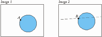
Figure 37: Epipolar line constraint
Because the circle in has no hard corners or features point B can only be positioned approximately visually. Using the epipolar constraint function it can still be accurately positioned though. Moving point B with the [Shift] key held down results in the epipolar line being shown in Image 2 (as in Figure 37) and movement of B being constrained to lie along this line. As the line intersects the clean edge of the circle it is now possible to accurately position B.
For this to work the epipolar geometry should be known. This means that a sufficient number of points should already have been calculated in the model before points are inserted and modified along epipolar lines as described above.
All selection points, lines and polygons (objects) within Geometra is done using the pick tool on the Edit toolbar so this tool must be activated before any selection is done.
To select an image point click on it. It will turn yellow to indicate it has been selected.
To select a line click on or near it's centre. The line will be shown in a red and white dashed pattern to indicate it has been selected.
To select a polygon click anywhere inside of the polygon. The polygon will be shaded in red to indicate it has been selected. Note that if any of the sides have also been defined as lines then clicking to close to the line which is the polygon edge will result in the line being selected instead of the polygon.
To select a number of objects in a rectangular area click on one corner of the area within which you wish to select and holding down the left mouse button drag to the opposite corner of the selection area. The rectangle enclosing the are will be shown on screen while dragging. When the opposite corner has been reached release the left mouse button and all the objects within the area defined will be selected and displayed as selected.
Using this area selection method is also a good way of selecting a single image point without accidentally moving it - simply select it within a small rectangular area.
Holding down the [Control] key while making a selection results in the selection being added to the previous selection. If [Control] is not held down while making a selection then all the previous selections are cleared and only the most recent selection is effectuated.
To un-select any selected objects it simply click elsewhere in the image, away from any objects and all selections will be cleared.
Lines can be inserted between image-points in the same image. If these image-points have been referenced (to image-points in other images) then these lines will also be displayed in other image windows as appropriate if line display is turned on. Lines will be displayed in the 3-D viewer if line display for that is turned on and the referenced points have also had their 3-D positions calculated by Geometra. Lines can be exported to DXF (default) and VRML files (optional) if desired.
To insert lines make sure the line tool is selected on the Edit toolbar. The line tool cursor will be displayed. Click on the point where you want the line-segment to start. Next click on the point where you want the line-segment to end. A black and white dashed line will appear between the two image-points. If a single line-segment was desired right-click anywhere in the image to conclude entry of this line. If additional line-segments are required click on the next image-points in the appropriate order and right-click after having clicked the last one.
On right-clicking to conclude the line entry all other image-windows and 3-D viewer windows will be adjusted as appropriate, depending on display settings.
To delete a line it must first be selected. Make sure the pick tool is the active tool on the Edit toolbar. Click on or near the centre of the line to be selected and deleted. The line will change from a black/white dashed pattern to a red-white dashed pattern to indicate it has been selected. Press the [Delete] key and the selected line will be deleted from the project and any image or 3-D viewer windows it may have been shown in.
Polygons spanned by 3 or 4 image-points can be inserted if these points are all present in the same image. If these image-points have been referenced (to image-points in other images) then these polygons will also be displayed in other image windows as appropriate if polygon display is turned on. Polygons will be displayed in the 3-D viewer if polygon display for that is turned on and the referenced points have also had their 3-D positions calculated by Geometra. Polygons can be exported to DXF (without texture) and VRML files (with or without texture) if desired.
To insert polygons make sure the polygon tool is selected on the Edit toolbar. The polygon tool cursor will be displayed. Click on the first corner point (an existing image point) where you want to start building the polygon. Next click on the second corner point of the polygon. Moving the mouse and cursor about now results in the triangle spanned by the two clicked points and the cursor position being shown in inverse video. Click on the third point of the polygon. If the desired polygon was the triangle now shown right-click and the polygon will be defined. If a quadrilateral was desired then click on the fourth corner point. No right-click is required to finish entering a quadrilateral.
On concluding the polygon entry all other image-windows and 3-D viewer windows will be adjusted as appropriate, depending on display settings.
Select the polygon or polygons (page * , Selecting objects) to be deleted. Press the [Delete] key and the selected polygon(s) will be deleted from the project and relevant image or 3-D viewer windows.
There are a number of options which influence what is displayed (or not) in image windows. For more information see also the section Keyboard shortcuts on page * and the section Options - Edit on page *.
Effective use of these options can make a great deal of difference, making working on Geometra faster, more effective and also more pleasant.
The most basic option is whether to display image-points or not. This option can be set in the Geometra Options dialog or toggled using the R key. Possible reasons for turning this option off could be as a part of turning off all display options to get a totally clear view of an image or images or it could be handy in deleting a group of lines or polygons without also deleting the points which span them. To do this make sure that the objects to be deleted are display but the image-points are not. With the pick tool select all objects in the relevant area and delete them using the [Delete] key. On turning image-point display back on the image-points will still be there as objects which are not displayed cannot be selected or deleted.
The option to display point numbers (via dialog or toggled using the N key) only has effect if image-point display is turned on as it is not sensible to display a point number of a point which is not displayed. This option can be very useful in tracking down incorrect references where an image point has simply been misplaced or two or more image points have been referenced together without them corresponding to the same world-point as they should.
In tracking down such errors it can also be useful to turn on the display of residual errors (via dialog or toggled using the E key). The residual is basically the difference between the position of a clicked image-point and the re-projection of the calculated corresponding world-point into the image. Therefore residual display only makes sense after calculating the model. Ideally this residual should be zero. In practice it never is.
In the example shown in Figure 38 it is the referenced point 18 which has been misplaced.
Points 16 and 22 do not display any visible residual error as they have been properly referenced and accurately placed. Point 18 has been misplaced it's location in the two images corresponds to two different world points. This problem can easily be solved by moving point 18 to the correct location in the left image. The displayed residual error will decrease as the point is moved, disappearing (at least visibly) as the point reached the correct location. After correcting such an error it is usually advisable to re-calculate the model.
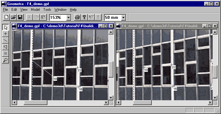
Figure 38: Residual error caused by misplaced image-point
As residuals on good models should be very small it is usually necessary to magnify the residual by a certain factor to make it visible (page *, Options - Edit).
Another option is whether to display lines or not. This option can be set in the Geometra Options dialog or toggled using the L key. This option is often used in conjunction with the option to display line lengths (toggled using the D key) to show dimensional information for an object (page *, Options - Edit).
There are a number of options which influence what is displayed (or not) in 3-D viewer windows. For more information see also the section Options - 3D Viewer on page *.
The most common of these are again accessible through keyboard shortcuts with L toggling display of lines, P display of polygons and, if polygons are displayed then T toggles whether they are displayed with (extracted) photo-textures or just shaded in uniform grey.
As is common with many applications Geometra provides an undo function which makes it possible to reverse editing actions which turned out not to be desirable. To undo an action either select Undo from the Edit menu or press [Control]-Z. The last action performed (providing it wasn't the removal of an image) will be undone.
Actions which can be reversed using the undo function are:
These actions can be also be undone sequentially, i.e. subsequent invocations of undo will undo editing actions in the reverse order in which they were originally performed.
The one editing action which cannot be undone is removal of an image from a project.
There are a number of circumstances which make it necessary to calculate or re-calculate a model. These circumstances are:
To have calculation performed select Calculate on the Model menu or click on the Calculate button on the main toolbar.
Before starting the calculation Geometra will do some basic checks to see if any conditions apply which make successful generation of a 3-D model less likely. If necessary warnings are issued.
While the program is calculating the text "Calculating..." is shown at the left of the status bar at the bottom of the Geometra workspace with the dots flashing. On completion "Done" will be displayed in the same place.
On completion of the calculation, if the largest residual error for any point in the project is larger than the threshold value set under the Calculation tab in the Options dialog (page *, Options - Calculation) then Geometra will show a warning informing the user which point this is and how large the residual error for this point is.
Due to the complex nature of the calculation which Geometra has to perform to find 3-D shape from the co-ordinates of referenced points it is sometimes possible for it to "get lost" and come up with a solution which makes no visual sense (even if it does in the mathematical sense of the calculation process). When this happens it will be immediately and visibly obvious when looking at the model in the a 3-D viewer window because the model will look nothing like reality. Conversely, if the model looks right in the 3-D viewer window then it will be as good as Geometra can make it.
If Geometra does come up with a solution which makes no visual sense then it can sometimes help to reset the calculation so it doesn't start looking for a new solution based on previous results (which are now wrong). To do this select Reset Calculation from the Model menu and then start the calculation again using either the Calculate entry on the Model menu or the calculate button on the main toolbar.
If the results are still wrong after trying this a couple of times then it may be wise to review the project to see if there are enough points in images taken from sufficiently different perspectives. Reviewing any warnings given at the beginning of the calculation can also be useful.
Very occasionally the calculation may take a very long time, seemingly to "hanging" the program. To abort such a calculation Select Stop Calculation from the Model menu. Resetting the calculation and/or adding or improving references may help the calculation run the next time.
The options to estimate and compensate for radial lens distortion dialog (page *, Options - Calculation) can be useful if the camera used suffers from strong radial lens distortion, i.e. if straight lines which don't pass through the centre of the image appear to be curved, the effect getting more pronounced towards the edges of the image. In order for the first order (k1) and second order (k2) radial distortion parameters to be estimated effectively a higher than usual number of referenced points is required. A low point count which will only just produce a visually correct Geometra model will not be sufficient to accurately determine distortion parameters - in such a case distortion parameter calculation is best turned off.
Having Geometra calculate the (exact) focal length of the camera used is usually a good idea. If the images in the project were taken with different camera zoom settings (focal lengths) or even with different cameras then it even becomes necessary for successful project completion. As with the calculation of distortion parameters (or any parameters) results will be better with more good referenced point sets.
Based on referenced points in images Geometra can determine 3-D shape but not scale. In order for measurements in the project to be correctly scaled it is necessary to tell Geometra the exact length of one line within the Geometra project. After that all measurements within the project will be correctly scaled.
To set the model scale select the line for which a length is to be entered. Then click on the Set Scale entry on the Model menu. The Set Model Scale dialog box appears. Enter the known length of the selected line in the appropriate box and click on the OK button. Dimensioning (Show Line Length) should now work properly and on hovering the pick tool over any line the length of this line should appear in the status bar at the bottom of the Geometra workspace.
There are keyboard shortcuts available both for when editing and when using the 3-D viewer. Use of these shortcuts can make the generation of Geometra models much quicker, operating the mouse with one hand, the keyboard with the other.
Fast switching about between images using the keyboard can be done by pressing 1 to switch to image 1, pressing 2 to switch to image 2 and so on. Other keyboard shortcuts are listed in Table 1.
Table 1: Keyboard shortcuts in image windows
|
Key |
Function |
|
A |
Display polygons in all image windows |
|
D |
Show line lengths (dimensioning) |
|
E |
Show residual error |
|
F |
Zoom to fit |
|
L |
Toggle line display on/off |
|
N |
Toggle number display on/off (only if reference display is on) |
|
P |
Toggle polygon display on/off |
|
R |
Toggle reference display on/off |
|
V |
Bring up a new 3-D Viewer window |
|
[Left] |
Move a selected image point left by one screen pixel |
|
[Right] |
Move a selected image point right by one screen pixel |
|
[Up] |
Move a selected image point up by one screen pixel |
|
[Down] |
Move a selected image point down by one screen pixel |
Table 2: Keyboard shortcuts in 3-D viewer windows
|
Key |
Function |
|
L |
Toggle line display on/off |
|
P |
Toggle polygon display on/off |
|
T |
Toggle texture display on/off (only if polygon display is on) |
|
[Left] |
Rotate model |
|
[Right] |
Rotate model |
|
[Up] |
Rotate model |
|
[Down] |
Rotate model |
|
[Home] |
Rotate model |
|
[End] |
Rotate model |
|
[Page up] |
Zoom in (magnify) |
|
[Page down] |
Zoom out |
Invoking the Tools menu and then selecting Options brings up a tabbed dialog window. Under the Edit tab you will find the edit window options as shown in Figure 39.
The meaning of the various components in this dialog are as follows.
The Show points check-box determines whether image points are shown (as crosses) in the images or not.
The Show lines check-box determines whether lines (if present) are shown in the image windows or not.
The Show polygons determines whether any polygons entered are shown in the images or not.
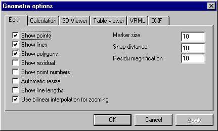
Figure 39: Options - Edit
Checking the Show residual check-box results in the residual being shown in the edit windows. The residual is basically the difference between the position of a clicked image-point and the re-projection of the calculated corresponding world-point into the image. Ideally this residual should be zero. In practice it never is. Image-points with a larger residual error may have been slightly misplaced or they may even be tied together by an incorrect reference.
As residuals on good models should be very small it is usually necessary to magnify the residual by a certain factor to make it visible. This factor is shown, and can be changed, in the Residual magnification box. It is usually set to 10.
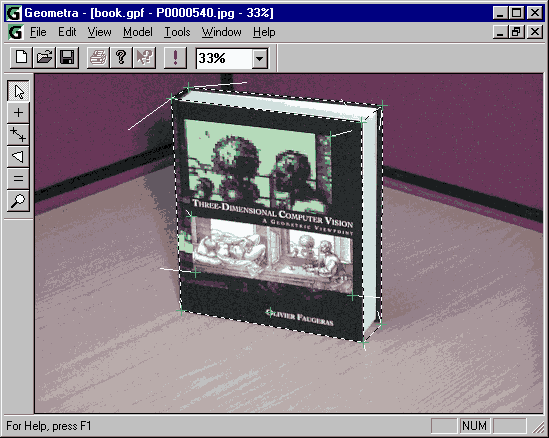
Figure 40: Residual errors at 30x magnification
In Figure 40 residual errors are shown at a magnification factor of 30 on the tutorial sample model.
With the Show point number box checked image-points are displayed with their reference number next to them.
Lines can be shown with their length displayed halfway along their length by checking the Show line lengths box.

Figure 41: Line length display
The Marker size box allows adjustment of the size of the markers which mark image-points.
The Snap distance box allows adjustment of the snap distance. When a point is clicked with, for example, the reference tool the Geometra software has to decide whether the user is pointing to an existing point or whether he is trying to insert a new one. If the point clicked is closer than the snap-distance to an existing image-point then that point is selected. If further than the snap distance from all existing image-points then a new point is entered.
Invoking the Tools menu and then selecting Options brings up a tabbed dialog window. Under the Calculation tab you will find the edit window options as shown in Figure 42.
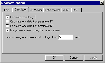
Figure 42: Options - Calculation
The calculation options influence the way the Geometra calculations are performed. With the Calculate focal length box checked Geometra calculates the focal length of the camera used. Usually a good idea unless this focal length is very accurately known. The two calculate lens distortion boxes determine whether radial lens distortion is calculated or not (this is usually not necessary in simple modelling applications). With the Images were taken with the same camera check box set identical parameters of focal length, etc, are assumed for all the images in the project.
The Give warning... box set the threshold value at which Geometra will warn about points with large residual errors. When on completion of a calculation the image-point with the largest residual error has a residual error of greater than the value set in this box, Geometra will issue a warning informing the user which point this is and what the associated residual error value is. Very often large residual errors correspond to faulty references (two or more image points referenced together when they don't correspond to the same world point) or just not quite accurately positioned image-points.
Invoking the Tools menu and then selecting Options brings up a tabbed dialog window. Under the 3D Viewer tab you will find the edit window options as shown in Figure 43.
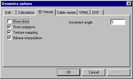
Figure 43: Options - 3D Viewer
Similar to the edit window situation Show lines and Show polygons boxes determine whether lines and/or polygons are shown in the 3-D Viewer. With the Texture mapping box checked the polygons are shown with the extracted photo-textures (as uniform grey when not checked).
Bilinear interpolation determines whether bilinear interpolation is used in image generation (higher quality) or not (higher speed).
The Increment angle box sets the rotation increment in degrees. Each time a model is rotated in the 3-D Viewer using one of the cursor keys it rotates by this number of degrees.
Invoking the Tools menu and then selecting Options brings up a tabbed dialog window. Under the VRML tab you will find the edit window options as shown in Figure 44. You can choose whether to have lines and/or polygons with or without texture mapping exported to your model using the Export lines, Export polygons and Export textures check boxes.
The Texture map height and Texture map width boxes are used to set the resolution (size in pixels) of the texture maps exported for each textured polygon.
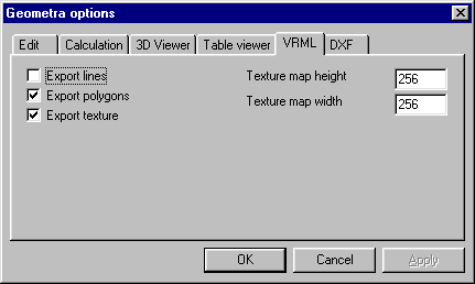
Figure 44: Options - VRML