
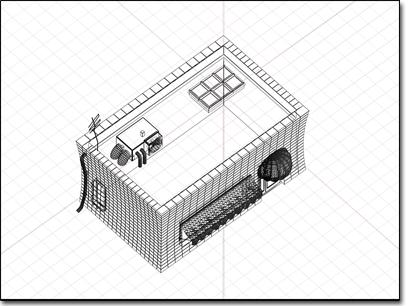
Axonometric view of the ice-cream shop
Axonometric views refer to the parallel projection of a 3D object onto a drawing surface (or computer screen). If the object is inclined so that three sides are visible, the projection maintains horizontal and vertical scale, but distorts diagonals and curved lines. Orthographic views, rotated user views, and isometric views are all forms of axonometric views.

Orthographic views of the ice-cream shop
Whether produced on computer or paper, most 3D design relies on orthographic views for accurate description of objects and their positioning. Maps, plans, cross-sections, and elevations are all orthographic views. In familiar terms, you might think of these views as "flat" or "straight-on," or as "looking at right angles."
Orthographic views are two-dimensional, each defined by two world coordinate axes. Combinations of these axes produce three pairs of orthographic views: top, bottom; front, back; left, right.
You can set viewports to the various orthographic views using the Viewport Right-Click Menu or keyboard shortcuts (see Change to ... View). For example, to set an active viewport to Right view, press the R key.
The label User appears on rotated axonometric viewports. In such views parallel lines remain parallel, no matter how extreme the foreshortening. You get a sense of three-dimensional relationship without the single viewpoint implied by perspective views.
You can change any view to a User view by doing one of the following:
Press U as a keyboard shortcut.
Use Arc Rotate to rotate an orthographic view. The viewport label changes to User as you do this.
Right-click the viewport label, and then choose Views > User.
Use the Layout panel in the Viewport Configuration dialog to change the viewport type. See Layout.
Isometric view of the ice-cream shop
Isometric is special case of axonometric, with the sides of the object equally inclined to the screen, producing equal foreshortening along the edges.
You can produce an isometric view in the program by rotating the home grid in the viewport. However, you cannot produce an isometric drawing view, which maintains scale along the diagonals and therefore has no foreshortening.