
Select an editable mesh object. > Modify panel > Selection rollout > Face/Polygon/Element
Select an editable mesh object. > Modify panel > Modifier Stack display > Editable Mesh rollout > Face/Polygon/Element
Select an editable mesh object. > Quad menu > Tools 1 quadrant > Sub-Objects sub-menu > Face/Polygon/Element
A face is the smallest possible mesh object: a triangle formed by three vertices. While a vertex can exist as an isolated point in space, a face cannot exist without vertices.
When in Editable Mesh (Face) mode, you can select single and multiple faces and transform them using standard methods. This is also true for the Polygon and Element sub-object levels; for the distinctions between face, polygon, and element, see Editable Mesh > Selection rollout. This topic covers the Edit Geometry rollout functions for these sub-object types; for other controls, see Editable Mesh.
Interface
Selection rollout
See Editable Mesh for information on the Selection rollout settings.
Soft Selection rollout
Soft Selection controls affect the action of sub-object Move, Rotate, and Scale functions. When these are on, gmaxapplies a spline curve deformation to unselected vertices surrounding the transformed selected sub-object. This provides a magnet-like effect with a sphere of influence around the transformation.
For more information, see Soft Selection rollout.
Edit Geometry rollout
Create: To create faces, click Create. All vertices in the object are highlighted, including isolated vertices left after deleting faces. Next, click existing vertices (the cursor changes to a cross, indicating that it's over a vertex) in a blank area of the viewport to create a new vertex on the active grid. You can start creating faces in any viewport, but all subsequent clicks must take place in the same viewport. At the Face and Element sub-object levels, a new face is created after every third click. At the Polygon sub-object level, you can continue clicking as many times as you like to add vertices to the new polygon. To finish drawing a new polygon, click twice, or click again on any existing vertex in the current polygon.
Delete: Deletes selected sub-objects.
Attach: Attaches another object in the scene to the selected mesh. You can attach any type of object, including splines and patch objects. Attaching a non-mesh object converts it to a mesh. Click the object you want to attach to the currently selected mesh object.
For further details, see Attach.
Detach: Detaches the selected faces as a separate object (the default) or as an element of the current object. The Detach as Clone option copies the faces rather than moving them.
You're prompted to enter a name for the new object. Detached faces leave a hole in the original object when you move them to a new position, unless you use the Detach as Clone option.
Divide: Subdivides faces into three smaller faces. This function applies to faces even if you're in Polygon or Element sub-object level. Click Divide, and then select a face to be divided. Each face is subdivided where you click it. You can click as many faces as you want divided, in sequence. To stop dividing, click Divide again or right-click.
Extrude & Bevel group
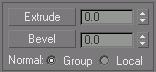
These controls let you extrude and bevel faces and polygons, as well as some elements. The latter are typically made up of several faces and do not fully enclose a volume. Extruding an element that fully encloses a volume, such as an attached sphere, simply translates the element.
Extruding faces moves them along a normal and creates new faces that form the sides of the extrusion, connecting the selection to the object. Beveling adds a second step that lets you scale the extruded faces.
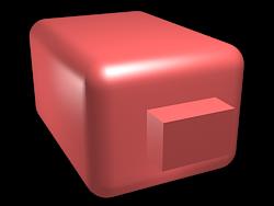
Chamfer box showing extruded face
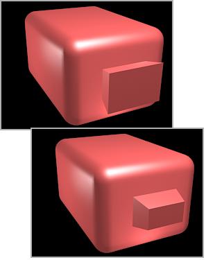
Extruded face beveled in two different directions
You can extrude and bevel faces by dragging or by using keyboard/spinner entry.
Extrude: Click this button, and then drag vertically on any face to extrude it.
When over a selected face, the mouse cursor changes to an Extrude cursor.
With multiple faces selected, dragging on any one extrudes all selected faces equally.
You can drag other faces in turn to extrude them while the Extrude button is active. Click Extrude again or right-click in the active viewport to end the operation.
Extrusion: This spinner (to the right of the Extrude button) lets you extrude selected faces outward or inward, depending on whether the value is positive or negative.
Bevel: Click this button, and then drag vertically on any face to extrude it. Release the mouse button and move the mouse vertically to bevel the extrusion. Click to finish.
When over a selected face, the mouse cursor changes to a Bevel cursor.
With multiple faces selected, dragging on any one bevels all selected faces equally.
You can drag other faces in turn to bevel them while the Bevel button is active. Click Bevel again or right-click to end the operation.
Outlining: This spinner (to the right of the Bevel button) lets you scale selected faces bigger or smaller, depending on whether the value is positive or negative. It is normally used after an extrusion for beveling the extruded faces.
Normal: With Normal set to Group (the default), extrusion takes place along the averaged normal of each contiguous group of faces. If you extrude multiples of such groups, each group moves along its own averaged normal. If you set Normal to Local, extrusion takes place along each selected face's normal.
Cut & Slice group
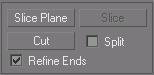
The Cut and Slice functions are available in Face, Polygon, and Element modes as of gmax. For details, see Cut & Slice.
Tessellate group
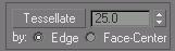
Use these controls to tessellate (subdivide) selected faces. Tessellation is useful for increasing local mesh density while modeling. You can subdivide any selection of faces. Two tessellation methods are available: Edge and Face-Center.
Tessellate: Click to tessellate selected faces, based on the Edge, Face-Center, and Tension (spinner) settings.
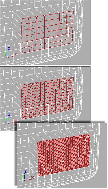
Original selection (top), tessellated once (center), and tessellated twice (bottom)
Tension: (Active only when Tessellate by Edge is active.) This spinner, to the right of the Tessellate button, lets you increase or decrease the Edge tension value. A negative value pulls vertices inward from their plane, resulting in a concave effect. A positive value pulls vertices outward from their plane, resulting in a rounding effect.
By Edge/Face-Center: Edge inserts vertices in the middle of each edge and draws three lines connecting those vertices. As a result, four faces are created out of one face. (To see this at the Polygon or Element sub-object level, turn off Display panel > Display Properties rollout > Edges Only.)
Face-Center adds a vertex to the center of each face and draws three connecting lines from that vertex to the three original vertices. As a result, three faces are created out of one face.
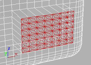
Set of polygons showing Face-Center tessellation
Explode group
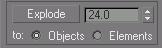
Use these controls to detach selected faces from each other.
Explode: Explodes the selected faces into multiple elements or objects based on the angles of its edges.

Exploded faces (white) removed from tessellated faces
The angle threshold spinner, to the right of the Explode button, lets you specify the angle between faces below which separation will not occur. For example, all sides of a box are at 90-degree angles to each other. If you set the spinner to 90 or above, exploding the box changes nothing. However, at any setting below 90, the sides all become separate objects or elements.
To Objects/Elements: Specifies whether the exploded faces become the separate objects or elements of the current object.
Remove Isolated Vertices: Deletes all isolated vertices in the object regardless of the current selection.
View Align: Aligns selected faces to the plane of the active viewport. In the case of orthographic viewports, this is the same effect as aligning to the construction grid when the home grid is active.
When aligning to a Perspective viewport (or Camera and Light views), the faces are reoriented to be aligned to a plane that is parallel to the camera's viewing plane (perspective viewports have invisible camera planes.). In these cases, the selection of faces is not translated but only rotated.
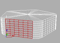
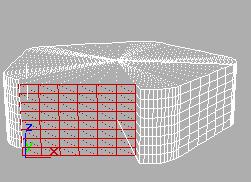
Selected faces in Perspective view (left); same faces aligned to Front view (right)
Grid Align: Aligns the selected faces to the current construction plane. The current plane is specified by the active viewport in the case of the home grid. When using a grid object, the current plane is the active grid object.
Make Planar: Forces all selected faces to become coplanar. The plane's normal is the average surface normal of the selected faces.
One application for Make Planar is making a flat side on an object. Normally, you would use a contiguous selection set. If the selection includes faces on various parts of the object, the faces are still made planar, but with distorting effects on the rest of the geometry.
Collapse: Collapses selected faces by welding their vertices to the vertex in the center.
Surface Properties rollout
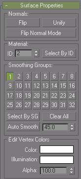
These controls let you work with face normals, material IDs, smoothing groups and vertex colors.
Normals group
Flip: Reverses the direction of the surface normals of the selected faces.
Unify: Flips the normals of an object so that they all point in the same direction, usually outward. This is useful for restoring an object's faces to their original orientations. Sometimes normals of objects that have come into gmax as part of a DXF file are irregular, depending on the methods used to create the objects. Use this function to correct them.
Flip Normal Mode: Flips the normal of any face you click. To exit, click this button again or right-click anywhere in the program interface.
Tip: The best way to use Flip Normal mode is to set up your viewport to display with Smooth+Highlight and Edged Faces turned on. If you use Flip Normal mode with default settings, you'll be able to flip a face away from you, but you won't be able to flip it back. For best results, turn off Ignore Backfacing in the Selection rollout. This lets you click any face and flip the direction of its normal, regardless of its current direction.
Material group
ID: Lets you assign a particular material ID number to selected faces (polygons, elements) for use with multi/sub-object materials. Use the spinner or enter the number from the keyboard. The total number of available IDs is 65,535.
Select by ID: Displays a Select By Material ID dialog that you use to enter a material ID number. Clicking OK selects the faces assigned that material ID. If Clear Selection is on, any previously selected faces are first deselected. If Clear Selection is off, the new selection is added to any previous selection set.
Smoothing Groups group
Use these controls to assign selected faces to different smoothing groups, and to select faces by smoothing group.
To assign faces to one or more smoothing groups, select the faces, and then click the number(s) of the smoothing group(s) to assign them to.
Select by SG (Smoothing Group): Displays a dialog that shows the current smoothing groups. Select a group by clicking the corresponding numbered button and clicking OK. If Clear Selection is on, any previously selected faces are first deselected. If Clear Selection is off, the new selection is added to any previous selection set.
Clear All: Removes any smoothing group assignments from selected faces.
Auto Smooth: Sets the smoothing groups based on the angle between faces. Any two adjacent faces will be put in the same smoothing group if the angle between their normals is less than the threshold angle, set by the spinner to the right of this button.
Threshold: This spinner (to the right of Auto Smooth) lets you specify the maximum angle between the normals of adjacent faces that determines whether those faces will be put in the same smoothing group.
Edit Vertex Colors group
Use these controls to assign the color, illumination color (shading), and alpha (transparency) values of vertices on the selected face(s).
Color: Click on the color swatch to change the color of vertices on the selected face(s). Assigning vertex colors at the face level prevents blending across the face(s).
Illumination: Click on the color swatch to change the illumination color of vertices on the selected face(s). This lets you change the illumination without changing the vertex's color.
Alpha: Lets you assign an alpha (transparency) value to vertices on the selected face(s).
The spinner value is a percentage; zero is completely transparent and 100 is completely opaque.