
Select an editable mesh object. > Modify panel > Selection rollout > Edge
Select an editable mesh object. > Modify panel > Modifier Stack display > Editable Mesh rollout > Edge
Select an editable mesh object. > Quad menu > Tools 1 quadrant > Sub-Objects sub-menu > Edge
An edge is a line, visible or invisible, forming the side of a face and connecting two vertices. Two faces can share a single edge.
When in Editable Mesh (Edge) mode, you can select single and multiple edges and transform them using standard methods. This topic covers the Edit Geometry rollout; for other controls, see Editable Mesh.
Procedure
To create a shape from one or more edges:
Select the edges you want to make into shapes.
On the Edit Geometry rollout, click Create Shape From Edges.
Make changes, as needed, on the Create Shape dialog that appears.
Enter a curve name or keep the default.
Choose Smooth or Linear as the Shape Type.
Turn on Ignore Hidden Edges to exclude hidden edges from the calculation, or turn this feature off.
Click OK.
The resulting shape consists of one or more splines whose vertices are coincident with the vertices in the selected edges. The Smooth option results in vertices using smooth values, while the Linear option results in linear splines with corner vertices.
When you region-select edges, all edges are highlighted, including hidden edges, which are displayed as dashed lines. As a default, the Create Shape function ignores the hidden edges, even though they're selected. Turn off Ignore Hidden Edges if you want to include the hidden edges in the calculation.
If the selected edges are not continuous, or if they branch, the resulting shape will consist of more than one spline. When the Create Shape function runs into a branching 'Y' in the edges, it makes an arbitrary decision as to which edge produces which spline. If you need to control this, select only those edges that will result in a single spline, and perform Create Shape repeatedly to make the correct number of shapes. Finally, use Attach in the Editable Spline to combine the shapes into one.
Original object (top) and object with edges selected (bottom)

Selected edges removed from original object (top) and unwanted edges removed (bottom)
Interface
Selection rollout
See Editable Mesh for information on the Selection rollout settings.
Soft Selection rollout
Soft Selection controls affect the action of sub-object Move, Rotate, and Scale functions. When these are on, gmax applies a spline curve deformation to unselected vertices surrounding the transformed selected sub-object. This provides a magnet-like effect with a sphere of influence around the transformation.
For more information, see Soft Selection rollout.
Edit Geometry rollout

Delete: Deletes selected edges and both faces attached to each edge.
Attach: Lets you attach another object in the scene to the selected mesh. You can attach any type of object, including splines and patch objects. Attaching a non-mesh object converts it to a mesh. Click the object you want to attach to the currently selected mesh object.
For further details, see Attach.
Divide: Lets you divide edges into two edges with a new vertex where you clicked. Click Divide, and then select an edge to be divided. Each edge is divided where you click it. You can click as many edges as you want divide, in sequence. To stop dividing, click Divide again or right-click.
Turn: Rotates the edge within its bounding. All mesh objects in gmax are composed of triangular faces, but by default, most polygons are depicted as quadrilaterals, with a hidden edge dividing each quad into two triangles. Turn lets you change the direction in which the hidden edge (or any other) runs, thus affecting how the shape changes when you transform sub-objects directly, or indirectly with a modifier.
Extrude & Chamfer group
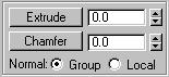
These controls let you extrude edges and bevel them using a chamfer function. Edge extrusion works in a fashion similar to face extrusion. You can apply both effects interactively (by dragging on edges) or numerically (using spinners).
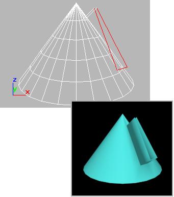
Extruded edges seen in a wireframe and a shaded viewport
Extrude: Click this button and then either drag to extrude the selected edge(s), or adjust the Extrude spinner to perform the extrusion. You can select different edges to extrude while Extrude is active.
Extrude Amount: This spinner (to the right of the Extrude button) lets you specify the amount to extrude the edge. Select one or more edges, and then adjust the spinner.
Chamfer: Click this button and then drag edges in the active object. The Chamfer spinner updates to indicate the chamfer amount as you drag.
If you drag one or more selected edges, all selected edges are chamfered identically. If you drag an unselected edge, any selected edges are first deselected.
An edge chamfer "chops off" the selected edges, creating new edges that move along the faces on either side by <chamfer amount>. Some vertex chamfering is done at the ends to make this behavior work with the rest of the mesh. New chamfer faces are created with the material ID of one of the neighboring faces (picked at random) and a smoothing group which is an intersection of all neighboring smoothing groups.
Chamfer Amount: Adjust this spinner (to the right of the Chamfer button) to apply a chamfer effect to selected edges.
Cut and Slice group
Lets you subdivide edges with either cut or slice tools to create new vertices, edges and faces. For details, see Cut & Slice.
Remove Isolated Vertices: Deletes all isolated vertices in the object regardless of the current selection.
Select Open Edges: Selects all edges with only one face. In most objects, this shows you where missing faces exist.
Create Shape from Edges: After selecting one or more edges, click this button to create a spline shape from the selected edges. A Create Shape dialog appears, letting you name the shape, set it to Smooth or Linear, and ignore hidden edges. The new shape's pivot is placed at the center of the mesh object.
View Align: Aligns selected edges to the plane of the active viewport. In the case of orthographic viewports, this is the same effect as aligning to the construction grid when the home grid is active. When aligning to a perspective viewport (including camera and light views), the edges are reoriented to be aligned to a plane that is parallel to the camera's viewing plane. (Perspective viewports have invisible camera planes.) In these cases, the selection of edges is not translated but only rotated.
Grid Align: Aligns the selected edges to the current construction plane. The current plane is specified by the active viewport in the case of the home grid. When using a grid object, the current plane is the active grid object.
Make Planar: Forces all selected edges to become coplanar. The plane's normal is the average surface normal of all faces attached to the selected edges.
Collapse: Collapses selected edges by welding the vertex at one end of each selected edge to the vertex at the other end.
Surface Properties rollout

These controls affect the visibility of the edges. Invisible edges (also called construction lines) appear in the viewports when Edges Only is turned off in the Display command panel, or when you're editing at the Edge sub-object level.
Visible: Makes selected edges visible.
Invisible: Makes selected edges invisible, so they won't be displayed in Edges Only mode.
Auto Edge group
Auto Edge: Automatically determines edge visibility based on the angle between the faces that share the edge, with the angle set by the Threshold spinner to its right.
Clicking Auto Edge can have one of three effects, depending on which radio button is active (Set means to make an invisible edge visible; Clear means to make a visible edge invisible):
Set and Clear Edge Vis: Can change the visibility of all selected edges depending on the Threshold setting.
Set: Makes previously invisible edges visible only if they exceed the Threshold setting; does not clear any edges.
Clear: Makes previously visible edges invisible only if they are less than the Threshold setting; does not make any edges visible.