LAYOUT DESIGN ROOMS EXAMPLE
*** using the 'layout design rooms' option from FILE / NEW to draw a plan ***

* If at any stage you go wrong * just click File / New and start again using the same drawing name to overwrite your previous work

Start the Fast Plans programme and select file / new, type test as the drawing name ( if ' client' is shaded ( in focus ), test will just overwrite it, if not make sure you type from the extreme left of the input ) and select the ôlayout design roomsö option, then select your preferred measuring system.
The design room dialogue box will now appear - change to suit yourself and clear by pressing enter or clicking the OK button. The title at the top of the screen will show test.LYT as this is now a layout view.
The Internal wall thickness dialogue box will appear , leave the input alone for now, and clear away.
The design room will appear in the bottom left corner of the screen ( your selected options may not appear until the room is finally drawn )
Move towards the middle of the screen, by placing the cursor in the room, holding down your left mouse button and moving the cursor ( and room ! ) towards the middle of the screen, then release the button.
Now add another room by clicking the design room icon ( or design rooms / new design room from the menu bar .
move the cursor into the new room,
for auto aligning hold down the left mouse button away from the centre text of the room, move to approximate position for the room and release the mouse button - if any edge of your room is within the merging distance of the original design room, the new room will auto align with it -
self aligning move

rooms now aligned and spaced wall thickness apart
if that did not work, move the cursor back inside the room, and move closer to the original room and release the left button
aligned
There are other ways to move design rooms, depending on which mouse button you use, and whether you click on the text area part of the room -
left mouse button, cursor on room text area - manual non aligning move
right mouse button, cursor in room - aligns with boundary rectangle if within merge distance = click on moving design rooms
You can also rotate, delete, shrink & expand design rooms click details
Once you have two rooms placed on screen, a boundary rectangle grid will appear, click for full details on design rooms you can toggle this on and off by clicking the layout grid icon.
At the bottom of the screen, the GUIDE LINE will now show the size and area of the boundary rectangle

HINT
You can use a spacer by naming a new design room space instead of a room name, useful for keeping design rooms a set distance apart (say for a passage way between rooms ), this space room is ignored when all the rooms are finished and redrawn.

FINISHING THE DESIGN ROOM LAYOUTS
On the demo you can only have up to 4 design rooms,
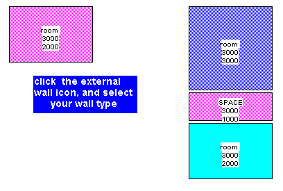
so add 2 more rooms, so that the screen looks something like this then we will mark the external walls.
MARKING THE EXTERNAL WALLS
Start by clicking on the external walls icon and selecting your wall type from the dialogue box
ready to mark external walls

Now the cursor changes to full size in the top left corner, the colour disappears from the rooms for ease of marking - if you want, click the layout grid icon to get a full screen grid to aid in marking the walls

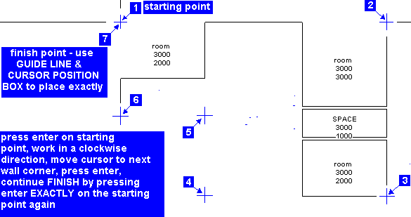
Unlike the normal 'draw external walls' option, for the 'layout design rooms' option you mark the inside line of the external walls - so some of your room corners will probably be corner marks Move the cursor to your starting point ( it does not have to be a room corner ) use the arrow keys to fine tune the cursor position (the cursor position box will show the distance from the top left corner of the old boundary rectangle, and press enter when correct, move clockwise (the cursor position box will show the distance )and press enter on all building corners (when the cursor is precisely on a room corner you will see the cursor lines alter ) and finish back at your starting point - follow the guide line and cursor position box to get that correct and press enter. Now the drawing will change to a .PLN plan view, centre itself, add dimensions, show the area and draw the rooms out with measurements shown as you directed in the design room dialogue.
All rooms drawn will allow for any external walls they butt to, in the case of a room drawing over part of an external wall, the room may not have been correctly aligned with the boundary rectangle. To over come that, select view / layout and your room layout will reappear, just use the right button to move the offending room in to the centre of the boundary rectangle very slightly and release the button, select the external wall icon and re mark the external walls

Mark the inside corner of your external walls, clockwise, finish back exactly at the original starting point and press enter ( watch the guide line and cursor position box figures to get this accurately ) otherwise the programme will not know you have finished marking the wall corners
Use the arrow keys to finetune the cursor position.
When the cursor is exactly over a room corner the room wall lines disappear.
NOTE
Marks 4, 5 and 6 are not on room corners, mark then how you want BUT to keep each wall square to the previous wall the cursor position box MUST have an angle of 0.00, 90.00, 180.00 or 270.00 and '0' for one distance for the new wall to be square to the previous wall
how your mark should look in the cursor position box :- mark 1 - press enter when the cursor lines cover the room corner lines
mark 2 - press enter when the cursor lines cover the room corner lines and the angle is exactly 90.00
mark 3 - press enter when the cursor lines cover the room corner lines and the angle is exactly 180.00
in this drawing we show the starting point marking, then follow the numbers around the drawing marking each corner marking the walls

mark 4 - press enter when cursor position box shows :- your distance from last mark, 0, 270.00
mark 5 - press enter when cursor position box shows :- 0, your distance from last mark, 0.00
mark 6 - press enter when cursor position box shows :- your distance from last mark, 0, 270.00
mark 7 - back exactly at the starting point, press enter when cursor position box shows :- 0, your distance from last mark, 0.00 and the guide line will show 0 , and the same distance ( may be a minus number ).

HINT
if you just want a room as a spacer, type æSPACEÆ this will show on the room layout as in the above drawing, but when you get the Plan view ( drawing below ), it will just be a vacant area - useful for passageways and for keeping rooms always a specific distance apart.
The layout view now changes to a plan view - ready for doors, windows etc.,
plan view


HINTS
If your layout is going to be larger than the screen, hold down the left mouse and move to the edge of the screen to auto scroll either a room or the wall marking cursor. You can also use zoom / fit on screen, or zoom / shrink by half before marking the external walls if you prefer.

You can always come back to your last layout (view / layout) and change it around and mark the walls again to get a new plan view - it will overwrite any existing plan view with the same name.

Customise If you want to change the merging ( self aligning ) distance - too large a distance may cause some confusion as the room may not align with the room you wanted it to - experiment with various distances, click customise/design room merge change the room colours, click customise/design room colours or change the layout grid, spacing and colour ,click customise/default layout grid

DRAWING UPPER FLOORS
Once you have the ground floor drawn, you can add the floors above,
click drawing floors above

SITE PLAN
You can now add the site location plan
click adding a site plan

TO FINISH
click FINISH DRAWINGS - EXAMPLE 3 to complete your drawing by altering the rooms to add cupboards, adding windows and doors adding fixed or more design rooms, library items, etc.,