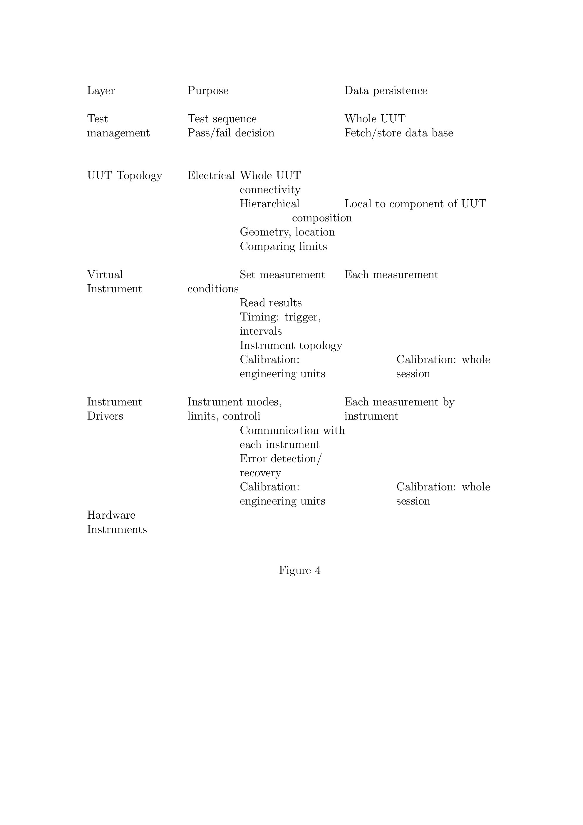
From the domain models, class hierarchies for the application domain classes were identified. Each layer had a different purpose (functionality), temporal duties, and persistence of its data. These properties are shown in Figure 4. The abbreviation UUT stands for ``Unit Under Test'' (i.e., the device on which measurements are being made).
The lowest-level layer contains the instrument drivers. There is a 1:1 correspondence between drivers and physical instruments. The next higher layer is the result of a design abstraction: the virtual instrument layer. It allows application domain measurements to be made by combinations of more primitive hardware instruments. The UUT Topology layer is actually a variable number of sub-layers which have the responsibility of agglomerating measured data. The classes in these layers mirrored the topology of the products being measured. Refer back to Figure 1 for an example. The top layer(s) provided management of the measurement sequencing and communication to other tasks. The interfaces between layers were defined as architecture standards for this application, and they were implemented using Abstract Base Classes (ABC's). An example of this class design is shown in Figure 5.
Following the design of the application domain classes, lower domain classes (such as service and computer science classes) were added to the design. They were mapped onto a client-server architecture containing three nodes as shown in Figure 6.