X-15 Research Results

Chapter 6

A Hypersonic Structure


PERHAPS NOWHERE ELSE are the broad, interdiscipiinary facets of hypersonic and reentry flight so apparent as in a close examination of the X-15 structure. The basic effect of any change in airflow, aerodynamic heating, or maneuvering loads is to alter the stresses within each structural element. In some places, the combination of stresses has permanently marred the once-sleek lines of the wings and fuselage. Some scars are penalties for incomplete understanding of the aerodynamic and thermal forces of airflow from subsonic to hypersonic speeds. Others were left by the oscillatory airflow that superimposed dynamic forces on already severe static-load conditions. The deepest scars are found where the interplay among these varied stresses intensified the effects of each. Yet, these scars are superficial, of the engineering-fix type. The basic structure has withstood repeated flights into the high temperatures of hypersonic flight.

Although many details of the stresses within a heat-sink structure were uncovered during the flight program, the major questions had to be answered during design and construction. The problem for the structural engineer would be relatively simple if weight were of little importance. For example, the essential difference between the weight of a diesel train and that of an airplane is that sufficient metal is used in the former to maintain uniformly low stress levels throughout the structure, while an airplane, in order to achieve minimum weight, maintains uniformly high stress levels. For the X-15, it was essential to achieve uniformly high stress levels within each load-carrying element for the many uneven and fluctuating load conditions of flight anywhere within the corridor, and with a reasonable margin of safety.

The compounding factor was the effect of aerodynamic heating. It required a reorientation of the structural designers' thinking, because the many interactions of a hot structure impose further stresses on a pattern already made complex by airloads. The designer must analyze and sum the individual stresses from static airloads, dynamit airloads, aerodynamic, and their interactions. Since the structure responds dynamically as well as statically, a complex chain of reaction and interaction faces the analyst.

Surprisingly, the force from aerodynamic lift that sustains or maneuvers the X-15 is not a major stress problem. The total lift force on the wings of the X-15 during reentry could be carried by the wings of the Spirit of St. Louis, in which Charles Lindbergh crossed the Atlantic. But this statement neglects the distribution of that force, the added stresses from airloads that twist the wing, and the dynamic loads. When these effects are included, the wing of the Spirit of St. Louis would be as incapable of withstanding the total airload during reentry as it would be vulnerable to aerodynamic heating.

The effects from aerodynamic heating are twofold: reduction in the strength of Inconel X as temperature increases, and distortion of the structure from uneven thermal expansion. A new element was also added to structural design, for with the heat-sink concept, the time of exposure became the critical parameter that established the amount of heat flow into the external structure when exposed to a 2500░ F airflow. In areas that carry only small aerodynamic loads, Inconel X can withstand considerably more than 1200░ F, perhaps 1600░ F. The sharp leading edge on the vertical fin has withstood 1500░ F, and one non-load-carrying section of the wing skin has successfully endured 1325░ F. These temperatures are experienced for only brief periods of time, however. Prolonged exposure would eventually cause these temperatures to be conducted to load-carrying members, and thus impair the structural integrity of the X-15.

The structural design requires a careful balancing between the amount of material required to carry the load and that needed to absorb the heat flow. On a typical flight, the structure near the nose experiences 20 times as much heat input as the aft end. In regions of high heat input -fuselage nose, wing leading edge, tail leading edge- solid bars of Inconel X are required to absorb the heat energy.

A factor important to design balance is that the maximum load and maximum heating temperature do not occur simultaneously. In actual practice, high temperatures have been explored in essentially level flight, with low aerodynamic loads; the high loads of reentry were encountered at relative low temperatures. But whenever Mach numbers greater than 4.5 are achieved, the thermal potential of the airflow can drastically affect the plane's strength. Structural failure could occur at even low load levels during prolonged flights at Mach 5 at low altitude where the heat flow is at a maximum.

The structural engineer is faced with another formidable design task in dealing with aeroclastic and aerothermoelastic problems. The root cause is the flexibility of the structure and the deflection that accompanies each stress. Although the X-15 isn't as flexible as the wing of a jet transport, the effects on it of even minute distortion can be far-reaching. The difficulty is that though structural deflection is not objectionable, it induces additional aerodynamic forces from the change in angle between the structure and the airflow. This redistributes the airload and results in a further change in pressure forces and deflection, which continues until the aerodynamic forces and structural resistance are in equilibrium. Thus the rigidity of the structure appreciably affects the load it is subjected to. While rigidity influences fuselage design to some extent, it was a prime factor in the design of the thin wings and tail surfaces. For they must have not only adequate resistance to bending but also adequate torsional rigidity to resist twisting.

At high speeds, the large forces acting on surfaces require the designer to analyze more and more exactly these elastic deformations. Yet the solution for complex flow patterns and deflection from thermal expansion often does not yield to analysis. Another consequence of flight to speeds above the transonic region is that the airflow is characteristically fluctuating, and causes buffeting and vibrations. In some instances, resonances, or self-excited oscillations between airflow and structure, are encountered. This phenomenon, called flutter, is extremely complicated, since resonances are possible in any combination of bending and torsional oscillations.

Aeroelastic problems began to play a prominent role in high-speed aircraft design soon after World War II. Prior to that time, aircraft structures usually were sufficiently rigid and speeds sufficiently low to avoid most aeroelastic problems. But such problems had been encountered frequently enough during flight -often disastrously- to stimulate many studies into the phenomena.

By the early 1950's, much had been learned about the interactions of aerodynamic-elastic-inertial forces through theoretical analysis and experiment. But much remained vague and unknown. Each increase in speed seemed to compound the problems. Even simplified theories to account for interactions required such complicated systems of equations as to preclude their practical use in the era before modern, high-speed digital computers. Designers relied upon wind-tunnel tests with dynamically-scaled models to study the aeroelastic response of the structure. They sometimes obtained final verification only through slow and tedious flight tests.

The X-15's extension of flight conditions to Mach 6 and large aerodynamic forces represented a step into many new aeroelastic areas. At the time of the design, there were no experimental flutter data for speeds above Mach 3, and an adequate aerodynamic theory had not been established. To this perplexity was added the question of the effects of heating the structure to 1200░ F. This high temperature not only reduces the strength but the stiffness of Inconel X, lessening its resistance to deflection.


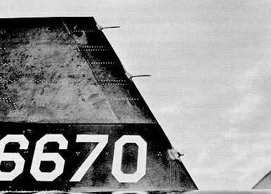
Pressure tubes in the leading edge of the X-15's upper vertical tail measure airflow conditions in the wake of the fuselage. The craft's instrumentation, elaborate despite weight and volume restrictions, measured pressure at 160 locations.


The thermal expansion of a hot structure reduces stiffness more markedly, however. The uneven heating of the structure produces large differences in the expansion of its various elements. The distorsion caused by this uneven expansion seriously increases the aeroelastic problems, for it can reduce stiffness as much as 60 percent.

Although some aeroelastic problems could be scaled for wind-tunnel testing, no facility existed for combined testing of aerothermoelastic problems during the design period. (Later, some full-scale tests were made in a new NASA facility to proof-test the vertical tail at Mach 7 and design temperature and pressures.)

A rather novel test program was undertaken to overcome this potentially serious lack. Small dynamic models were tested in the "cold" condition, with their stiffness reduced to simulate the hot-structure condition. The amount of reduction in stiffness was determined from laboratory tests of structural samples subjected to the anticipated load-temperature variation with time during flight. A very extensive test program was carried out, including tests in eight different wind tunnels, at speeds to Mach 7.

From these various design conditions and procedures, a structure developed that bears many similarities to, as well as differences from, those of previous aircraft technology. The basic structure is a conventional monocoque design, in which the primary loads are carried in the external skin of the fuselage and wing. The fuselage skin also forms the outer shell of the propellant tanks. Thus, it must withstand the stresses from propellant weight as well as from internal tank pressurization. To absorb heat input, skin thicknesses on the forward fuselage are about three times those near the tail section. Fifteen feet aft from the nose, skin thickness is sized by load, rather than by heating, and is comparable to that of aluminum structure.

An important feature of the structural design is that only a small amount of the heat absorbed by the external skin is conducted, or radiated, to the internal structure. Consequently, much of the internal structure of the fuselage is of titanium and aluminum. Extensive use is made of corrugations and beading, to allow for uneven thermal expansion between external skin and internal structure.

The wing presented a difficult design problem, to account for uneven heating from leading edge to trailing edge and between lower and upper surfaces. At high angles of attack, inconsistent heating typically subjects the wing's lower surface to temperatures 400░ F higher than those of the upper surface. The result of higher heating at the leading edge and lower surface is that these two surfaces try to expand faster than the rest of the wing. Thus, the wing structure had to be designed to allow for this expansion without deforming to a large extent, while, at the same time, carrying rather large airloads. A balance was achieved by allowing some expansion of skin to alleviate a part of the thermally induced stresses, and by the use of titanium internal structure, which has a higher elasticity than Inconel X. The internal structure provides enough restraint between attach points to give the hot wing surfaces a tufted-pillow appearance as they try to expand. Corrugations in the internal structure allow it to flex enough to keep skin stress within tolerable limits.

The movable horizontal tail presented another knotty structural-design problem. Aerothermoelastic effects were severely complicated, since the movable surface could not be rigidly attached to the fuselage along the length of the inboard end. All loads had to be carried through the single pivot point, which made much more difficult the problem of maintaining adequate torsional rigidity. This problem was so predominant, in fact, that it was the basic factor governing the design of the horizontal tail. In order to achieve adequate stiffness, the external surface here is restrained much more than the wing surface, and the pillowing effect at high temperature is quite marked. These are transient effects, however; no permanent deformation has been observed.


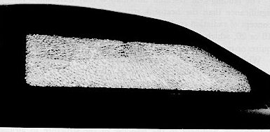
Temperature-indicating paint strikingly reveals the uneven heating to which the X-15's heat-sink wing structure was subjected during a high-heating mission. Dark areas indicate the higher temperature. Light areas reveal internal structure.


Despite the general information gained during design and construction, several interesting additional problems were uncovered during flight. It is not unusual that these problems occurred in regions of large aeroelastic and aerothermoelastic interactions, or in regions of large thermal stress.

A classical example of the interaction among aerodynamic flow, thermodynamic properties of air, and elastic characteristics of structure was the local buckling at four locations, just aft of the leading edge of the wing, during the first significant high-temperature flight to Mach 5. This buckling occurred directly back of the expansion slots that had been cut in the leading edge of the wing. The slots induced transition to turbulent flow, with an accompanying large increase in heat flow to the surrounding structure. The resulting thermal stresses in the skin because of hot spots and uneven expansion produced small, lasting buckles in the wing surface. From this one flight, the problem of even small surface discontinuities was revealed, and the mechanism of the problem analyzed. Fortunately, the buckles could be removed, and relatively minor modifications were made to eliminate a recurrence. Additional expansion slots were cut, and thin cover plates were made for all slots, to prevent turbulent flow.


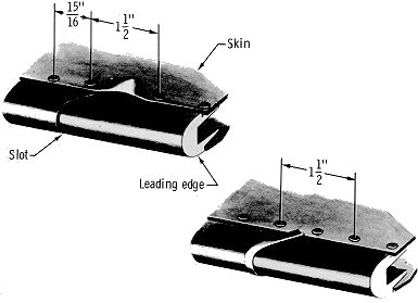
Top drawing shows a typical buckle in the wing skin of the X-15, caused by uneven expansion between the leading edge and the area directly behind it in hot airflow at hypersonic speed. Bottom drawing shows how covering the slots with small Inconel tabs and adding a rivet prevented recurrence of the buckling.


Another problem from turbulent flow has been the cracking of the canopy glass. The canopy protrudes into the airflow behind the nose shock wave, and, in combination with the flow around the fuselage, produces an unpredictable tangle of turbulent flow conditions. Although initial analysis indicated that the glass would be subjected to maximum temperatures of 750░ F, more detailed studies revealed that the glass would be heated to the same maximum temperatures as the Inconel X structure. Structural integrity was seriously threatened, in consequence. Although the solution was a dual glass design, with an outer pane of high-temperature alumina-silica glass, both inner and outer panes have cracked in the course of the flight program. Fortunately, they have never cracked simultaneously on both sides of the canopy, nor have both panes cracked on one side. The failures were due to thermal stresses in the glass-retainer ring. Several changes in its shape and material to minimize hot spots have eliminated the problem. It has served to emphasize the difficulty of predicting thermal strsses for this condition. It remains an area of deficiency in research information.


A noteworthy scar of the X-15's first flight to Mach 6 was this cracked outer panel on the right side of the windshield. Investigators found that thermal stresses higher than expected in the metal retainer holding the glass had caused the cracking.


The aeroelastic-model program carried out during design successfully eliminated surface flutter. However, the lightweight design resulted in some very thin skins, which have proved susceptible to a variety of vibration, noise, and peculiar flutter problems. Most of these were overcome during extensive ground-testing and captive B-52 flight tests. But one of the many unusual facets of flutter still plagued the flight program. This was the fluttering of individual external skin panels rather than an entire surface. It was first encountered on the fuselage side fairings, later on the vertical tail. Previous supersonic research had made it known, but it was not predicted to be a problem for the X-15. However, it was encountered at moderate supersonic speeds, and restricted flight operations over much of the corridor until a solution for it was found.

An extensive wind-tunnel and analysis program was carried out in conjunction with X-15 flight tests. By the time the program was completed, 38 panels on the airplane had been found susceptible to flutter. By good luck, relatively minor modifications, which stiffened the panels and increased their resistance to fluctuating airflow, eliminated the problem. Since this was the first occurrence of panel flutter to be well documented and explored, it stimulated much research into the basic mechanism.

More than 75 flights of the X-15 to high temperatures have demonstrated the soundness of the basic load-thermal-stress analysis. Much remains unknown about the magnitude of the individual airload and thermal stresses and deflections within the structure, however. For design, these unknowns were overcome through ingenuity and judgement in introducing assumptions for a simplified model of the structure. Sometimes, a simple beam suffices as a model. But researchers continue to try to develop models that will yield exact solutions for the distribution of load stresses and thermal stresses. For complex structure such as the X-15, it is a very difficult analysis problem trying to match actual responses to their model. It requires the use of high-speed digital-computer techniques.

Structural loads at the very lowest end of the flight corridor, the landing, have also received much study. The X-15 represents a new class of reentry vehicles, for which the externally stored landing gear must be able to withstand high temperatures from aerodynamic heating, in addition to normal landing loads. The landing gear developed to meet these requirements for the X-15 is unusual. On a normal airplane, primary impact loads of landing are absorbed by the main gear, located close to the plane's center of gravity. But the extreme-aft location of the main landing skids on the X-15 produces dynamic-response characteristics during landing that are as unusual as the gear itself.

The primary cause of the unconventional response is the craft's downward rotation onto the nose gear immediately following the main gear's touchdown. Significantly, this movement onto the nose gear causes a subsequent rebound onto the main gear, providing a much higher load there than that at initial touchdown. In addition, the nose gear encounters loads that are two to three times greater than at either of the main-gear skids. Another unique feature is that the gear loads achieve about the same maximum level whether the pilot "greases-it-on" or lands with a high rate of descent. These new gear characteristics have not been without problems. Much study and analysis of the dynamic response of the airplane during landing has led to strengthening the gear and back-up structure and modifying the nose gear so as to provide greater energy absorption. The concept represents a distinct state-of-the-art advance for high-temperature, lightweight landing gears.

The landing-gear research information may have more lasting significance than the heat-sink structural development. A new concept of radiation cooling has been developed for flight to Mach 10 or 20, which limits structural temperatures to 3000░ F yet requires no more structural weight than the X-15 has.

While the heat-sink concept now appears to have limited future application, it has admirably served a vital function for the X-15 program. The successful development of the concept has made it possible to explore hypersonic-airflow conditions of 2500░ F with confidence. Certainly, the early philosophy that more could be learned from a hot structure has borne fruit. And, of course, much information pertinent to the response of the structure to airload and thermal stress has universal application. Deficiencies in research information have been pinpointed for the canopy, panel flutter, and aerothermoelastic effects. Although some details are still obscure, engineers have a clearer understanding of the complex interactions between local airflow and structural response.

The success of this structural development is shown by the fact that speeds of Mach 6 and temperatures of 1200░ F have been probed repeatedly. In addition, flights have been made to the high-air-pressure conditions at the lower boundary of the flight corridor between Mach 5 and Mach 6, which produced a maximum temperature of 1325░ F. Thus, the full speed and temperature potentials of the X-15 have been achieved.

While the design-altitude goal of 250 000 feet has also been achieved (and actually exceeded by 100 000 feet), the full altitude potential of 400 000 feet has not been attained. The limit for flight above the corridor, however, is a compounding of many factors other than airloads and thermal effects. In fact, relatively low temperatures are encountered during a high-altitude flight, and thermal effects are of only minor importance. The primary limiting factors are the conditions encountered during reentry. These include consideration of over-all airplane response to the effects of structural load, aerodynamic flow, control system, and pilot control. Since these effects are transient in nature, reentry flight represents a difficult compounding of the dynamic response to flight to extreme altitudes.