Proceedings of the X-15 First Flight 30th Anniversary Celebration

X-15 Hardware Design Challenges


Dr. Harrison A. Storms, Jr.


Thank you, Ken. It is truly a great privilege to be a part of this 30th anniversary of the X-15. To review some of the history, it should be noted that the X-15 was participated in by four organizations (fig. 1). First was the Air Force, who supplied most of the money and took care of the contractual duties. Second, the Navy, who supplied some of the funds and was primarily a consultant and observer. (At least that's the way it appeared to me.) Third was the NASA, who technically ran the program, accomplished the wind tunnel tests, and most of the flight tests. Last was North American Aviation, Inc., who supplied the engineering and manufacturing talent to put the project together. NAA also did the early flight testing.

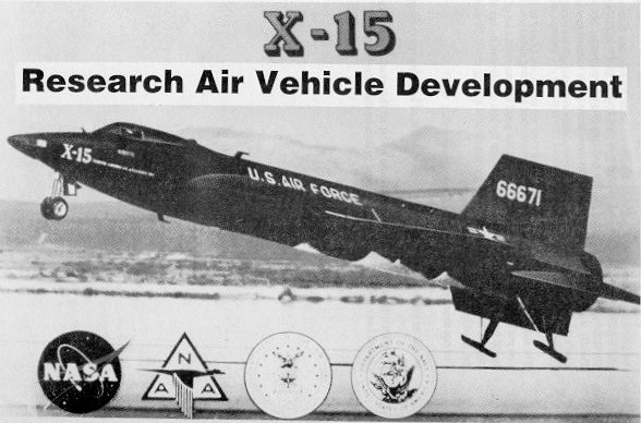
Figure 1. The X-15 aircraft.


Figure 2 calls out some of the official goals for the program. This program was the first step of any magnitude that would put the national flight research effort a good distance performancewise beyond the then production military aircraft or even those of today.

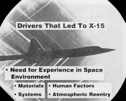
Figure 2. Drivers that led to the X-15 aircraft.


As indicated on figure 3, the NASA is beginning to address some of the manned requirements for space travel. Obviously, one of the most critical phases of this is the transition between pure space operation and atmospheric operation and what would be impact on manned requirements.

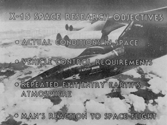
Figure 3. X-15 space research objectives.


Figure 4 gives the data on final contractual requirements. Here is a good point to deviate a bit. Originally, the mother plane was to be a B-36. However, the Dryden Flight Center group at Edwards felt that the maintenance on the B-36 would dominate the program and recommended a change to a B-52. Hartley SouI6 agreed, and we ended up with a B-52. I can't say enough about how well, in my opinion, Hartley did his job. He was a very outstanding program manager and has been greatly neglected in recognition. I feel that even though it would be posthumously, an appropriate award is in order to set the record straight. Mr. Soule gave us our instructions sort of like this, if my memory is correct: "You have a little airplane and a big engine with large thrust margin. We want to go to 250,000-ft altitude and Mach 6. We want to study aerodynamic heating. We don't want to worry about aerodynamic stability and control, or the airplane breaking up. So if you make any errors, make them on the strong side. You should have enough thrust to do the job." And so we did.

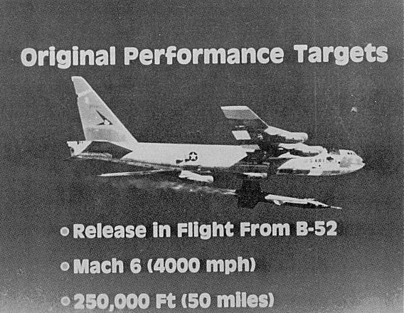
Figure 4. Original performance targets.


The next figure (fig. 5) is a representation of the design mission, which is self explanatory.

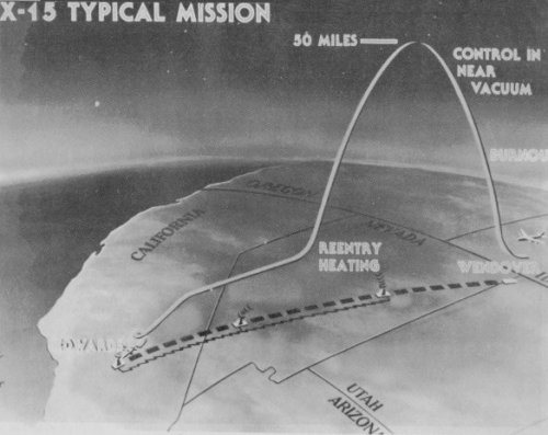
Figure 5. X-15 typical mission.


Figure 6 gives the overall size and weight of the X-15.

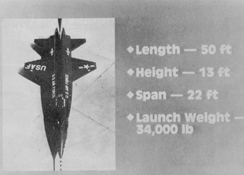
Figure 6. X-15 dimensions and weight.


In figure 7 we get to where you can see some of the internal arrangements, and I will point out some of the points of interest. First, starting at the nose of the X-15, you will note the location of the pitch and yaw thrusters. These are powered by passing hydrogen peroxide over a catalyst and turning it into a high-pressure, high-temperature gas that is expelled through a nozzle producing a thrust of 40 to I 10 IN There are eight of these thrusters located in the nose. There are two of them located on both the top and bottom of the nose for pitch control, and another pair are located on either side of the nose to produce the left and right yaw control. Moving aft, we pass the nose gear and cockpit. Behind the pilot, note the location of the auxiliary power units (APU's). There are two of these units mounted on a bulkhead. They are again powered by hydrogen peroxide, which drives a turbine that supplies the energy that produces all the hydraulic and electric power for the ship's service.

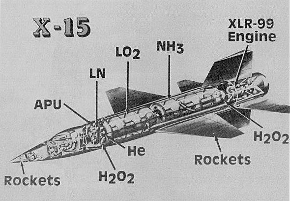
Figure 7. X-15 internal arrangements.


Now there is one part of the configuration that has caused more comments and questions than anything else. That is the fairing, which starts aft of the cockpit and runs to the wing and on to the tail. I would love to have some far-out aerodynamic theory for this piece of structure that would say that this was the reason why the X-15 worked so well at high Mach number, but, unfortunately, it was just a necessary evil. If you will note, the aft portion of the fuselage is fully loaded, first with the oxygen tank, second the ammonia tank, and then the engine. Now, how do you get electric power, hydraulics, and control cables from the cockpit to the wings, tail, and the back of the fuselage? The answer is the much questioned side tunnels or fairings, if you prefer. The only problem that was experienced with these fairings was that they vibrated under load and had to be reinforced.

On the outer wing you will note some additional thrusters. Those are the same type of control thrusters that are found on the nose, except that these are used for roll. There are two thrusters on each wing, one up and one down. As the pilot requires roll, the upward thruster fires on one wing and the downward thruster is activated on the other wing. This gives a roll with little or no pitch correction required. We now have our space-type controls complete.

The wing is usually thin. It has a thickness of only 5 percent. There is a plain flap, but no aileron.

The roll control and pitch control for the X- 15 during the in-atmosphere flight are both supplied by the horizontal tail. This tail has no elevators, but each side moves as a complete unit. The right and left side move symmetrically for pitch control and asymmetrically for roll control. I believe that the X-15 and F-107 are the first aircraft to use this type pitch and roll mechanism and to employ an irreversible control system with an artificial feel and stability augmentation.

The vertical tail also totally moves as one unit to produce the yaw control. The reason that the airfoil of the vertical tail is a half diamond is to allow sufficient internal space for structure and controls. The lower vertical area or ventral tail is in two parts. The bottom portion of the lower vertical may be dropped before landing and reused. The reason for this was the result of many conferences. First, there was concern about the static and dynamic directional stability at the high Mach numbers and high angles of attack; secondly, there was concern with the high concentration of mass along the thrust axis as compared to the wing axis. If we were to be required to improve the directional stability in the future, it seemed prudent to make the necessary provisions early to reduce any program impact. Our overdiligence in this matter was prompted by the adverse experience we had gone through on the F-100. Since we did not have sufficient data to give us the answers, we strongly recommended the droppable addition to the ventral fin. If it turned out that it was not required, it was easy to leave it off. However, if it were required and not available, this could cause a fair program delay. In short, it was insurance.

The other part of the vertical tail that has caused some comment are the dive brakes. The usual remark is why have dive brakes on a research vehicle? Or what are you going to bomb? The answer is that they are used as an aid in energy management. They are located on the aft portion of the vertical tail next to the fuselage. The purpose of these are purely for energy management as it was pointed out. It must be remembered that the basic mission was to launch at Wendover, Utah, climb and burnout, reach an altitude of say 50 mi, do whatever tests are called for, start a reentry, and land at Edwards. A large portion of this mission the pilot is flying at supersonic speeds of approximately two to five times the speed of sound. Most of the time he is really a supersonic glider. The target landing spot is Edwards where there is sufficient good lakebed. At low speeds, his L/D approaches that of a brick, and without power he must arrive at the right place to make his landing. The pilot does not have a lot of second chances for waveoffs, go arounds, and the like and must pay attention to his energy management. There is also another consideration and that is of obtaining data at the correct altitude and Mach number and aircraft attitude. This can also require that special attention be paid to the energy management problem.

Now looking at the forward part of the fuselage, you will observe the nose gear location. This has special problems that we shall call out later.

The aft landing skids have been questioned many times. But if you can figure out how to put a conventional gear into a 5-percent-thick wing and struts long enough to reach the ground in the landing attitude without losing the back end of the fuselage, be my guest! The current skids were located, as you will note on other figures, as the best solution to a difficult problem from a weight, temperature, and simplicity point of view.

This landing configuration was made possible for two fundamental reasons. First, there is no requirement for the X-15 to take off under its own power; it is always launched from the B-52. Secondly, it was only required to land on the Edwards Air Force lakebed or an equivalent terrain. As it turned out, the current solution to the configuration problem was a reasonable compromise.

Figure 8 covers the schedule that was realized for the project and is self explanatory and really does not need any further comments. It is here as a matter of record. Figure 9 indicates the categories that our development problems are concerned with at this point.

Figure 8. X-15 development milestones.


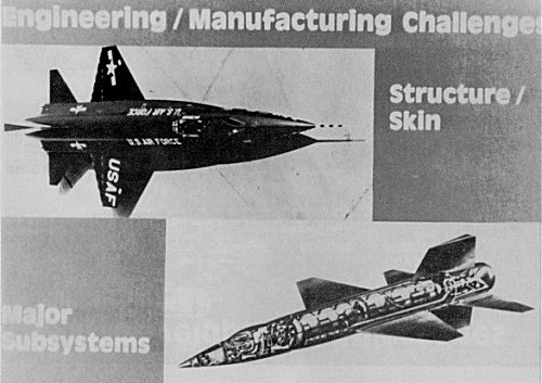
Figure 9. Engineering/manufacturing challenges.


Starting with the structural problems, figure 10 divides the aircraft into several sections.

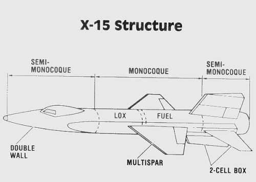
Figure 10. X-15 structure.


Our next figure (fig. 11) shows some of the typical configurations in both shape and material that are represen tative of various areas. I would like to direct your attention to the amount of titanium that is used. At this point in time information on welding, stress relieving, and forming titanium was scant, to say the least. It was also necessary to obtain similar data on Inconel-K It has not been generally recognized that about 70 to 80 percent of structure of the X-15 are welded assemblies.

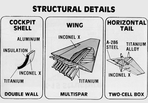
Figure 11. X-15 structural details.


Figure 12 points out that the X- 15 required two types of engine installations to be concerned with. The original intent was to install only the XLR-99, which was a throttleable rocket engine producing about 50,000 lb of thrust. However, this engine fell considerably behind schedule and something had to be done to keep the overall project in motion. It was decided to make an interim installation of two XLR- 11 engines. This would produce approximately one quarter of the XLR-99 thrust. However, it would be sufficient to obtain performance in the Mach number range of 2 to 3, which would allow the debugging of the airframe due to any problems, such as stability and control, or operational deficiencies that might occur without having any powerplant development and installation problems to distract the effort since these were proven engines used on the earlier X-type aircraft.

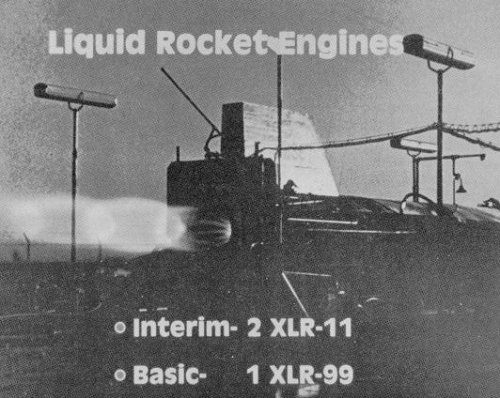
Figure 12. Engine installations required by the X-15 aircraft.


Before I continue, I would like to comment on the cockpit and human factors subsystem. The cockpit was extremely strong, as mentioned earlier, and it contained an ejection seat and had a standard control stick plus a side controller in addition to all the required flight instruments. The cockpit pressurization and cooling system utilized nitrogen to minimize any possible fire hazard. The pilot's pressure suit also used nitrogen for pressurization and cooling. However, at the neck there was a dam to prevent the nitrogen from entering the helmet area. The helmet was supplied with pure oxygen. As far as I know, most of the pilots in case of emergency at high altitudes and speeds considered their best course of action would be to stay in the cockpit and take advantage of its strong structure for its protection as long as possible until they reached more moderate altitudes and velocities and then use the ejection system. They held this opinion, in spite of the fact that both their suit and ejection seat had been qualified for the extreme conditions of high dynamic pressures and Mach numbers. Fortunately, none had to make that decision. The only concern that I ever had with this equipment was with the pilot's neck seal or dam, since a leak here of any magnitude could be extremely dangerous or fatal as there was no positive way to monitor the seal's integrity or to give the pilot any warning of impending danger.

Now, turning to some of the other subsystems, we will first review the hydraulic system (fig. 13). This system had three major hurdles to clear in development. The first challenge that surfaced was the basic X-15 mission and the temperatures involved and the effect that had on any hydraulic fluid plus the associated impact on the seals and "0" rings. After considerable work with the industry and an intensive testing of various candidate products, Oronite 8515 was finally selected. This material not only performed well at the higher temperatures, but also its use resulted in greatly reduced "0" ring swelling. These two characteristics were a major step forward in obtaining an excellent system.

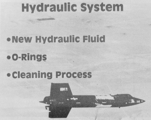
Figure 13. Hydraulic system challenges.


Another associated problem was the finding of a satisfactory diaphragm material to use in the accumulators. Due to the combined environment caused by the selected hydraulic fluid and temperature, the diaphragm material would break down and render the total system unusable. After a relatively involved research program in the NAA laboratories, a material was finally derived that would meet the requirements. At this point things were looking pretty good, except it turned out that to make the system operate properly with the desired reliability, the total circuit had to be surgically clean. We now felt we could design a satisfactory system.

Figure 14 calls to mind that the auxiliary power unit had some serious problems. A good share of the difficulties arose from the use of hydrogen peroxide as the propellant. By the time it entered the turbine, the temperature was high, about 1350 'F, the pressure was high, and it was very corrosive. Also, the bearings were not rugged enough to really support the operation that resulted from the environment. Further, the installation was not suitable as designed. The propellant would cause the unit to become slightly unbalanced and the resulting vibration would quickly destroy the bearings, causing extreme vibrations. Now remember that the X-15 had two APU's mounted on the same fuselage bulkhead located directly behind the pilot. This bulkhead would transmit the vibration from one APU to the other and the second unit would soon be destroyed. This sounds like quite a mess, but at least knowing your problems is half the fight.

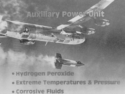
Figure 14. Auxiliary power unit challenges.


The subcontractor strengthened the unit and put in better bearings. The NAA project group markedly reinforced and strengthened the bulkhead. As a result, we ended up with an extremely reliable unit. This subsystem is one of the most important units in the X- 15 as it must supply all the electrical and hydraulic power from launch to landing. Any time this system goes out, the pilot has neither control nor communications and a good share of his instruments are inoperative. His only recourse is to leave the vehicle. Fortunately for all 199 flights no drastic action was required.

Figure 15 calls our attention to the ballistic flight controls. Since we have discussed these previously in fair detail, it probably is not productive to go into this any deeper.

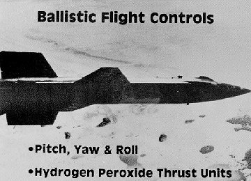
Figure 15. Ballistic flight control features.


Figure 16 shows the X-15 in the landing attitude with nose gear and rear skids extended. Before I become involved in this problem, I would like to go to the start of the NAA flight program.

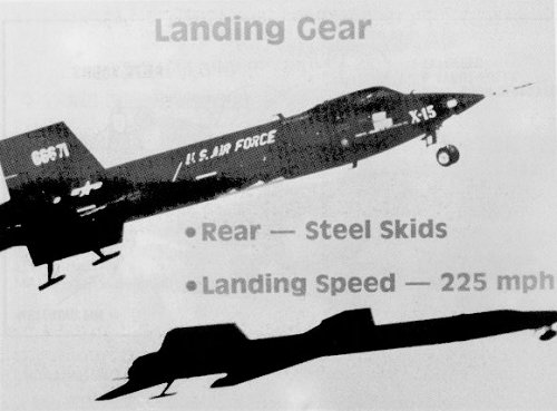
Figure 16. X-15 landing gear concept.


Before any flights were attempted, we had meetings with the Dryden flight planners and Hartley Soule to determine out of the many data measurements to be transmitted from the X-15 to the ground what information was required to be acceptable to permit a successful launch of the aircraft. It ended up that there were about 50 critical measurements that would be required before a launch would be permitted. Further, all of the critical data received had to be in the "green" area of acceptability. There were some additional conditions that NAA imposed on itself as to the method of conducting their portion of the flight test program that were as follows:
  1. We would not go beyond the preprograrnmed test plan, no matter how successful the test had gone, until we had studied the recorded data and concluded it was safe to do so.
  2. In building up to a launch, if all does not proceed on schedule due to some technical problem, we would be able to go into a hold mode and attempt to locate the cause. We would only stop this action when the problem required a shutdown to get it rectified, or by a decision that all was accomplished that was possible and it was in the best interests of the program to secure the action.
The NAA part of the flight program was in the first section and was primarily to check out the total operational system. At this point only the small engines were available; that was the XLR- I I type. The first test that we were to make was a glide flight from about 30,000 or 40,000 ft to the lakebed. This obviously required that both APU units had to be operational with some confidence that they would stay that way. It was like pulling teeth getting the program started, There were many equipment problems and major problems with the APU's and their installation. As mentioned earlier-the bearings, the backup structure, and the like.

A typical launch attempt would start the night before, and crews would work all night preparing the X-15 and fueling it. About 8 a.m., Scott Crossfield would be in his flight gear and, after walking around the operation, get into the cockpit and start his checkout. Scott would stay in the ready condition as the countdown continued. This, unfortunately, might be as late as 3 or 4 in the afternoon before the B-52 would be allowed to take off. By the time they had reached launch altitude and attempted to hold for the required length of time with all systems in operation, sometime during this period a regulator would fail, a valve would fail, or the bearings on one or both APU's would go out. Then back to Edwards. When Scott returned, we would be scheduled to go to a press conference and meet many tired, and by that time somewhat edgy, reporters that always wanted answers that were just not available. These were not happy meetings for any of the participants.

Shortly after about the fourth such encounter, I was gathered up by General John McCoy of Wright Field and taken over to Mr. Kindelburger's office, the then NAA chairman of the board. The general explained that the country was in a bad spot with the Sputnik success and that our false starts were not very much of a positive boost to the national position. In short, "when were we going to launch that X-15?" This one time in my life all eyes were on me. Not the most desirable position. The answer that I gave was to go over the conditions that we and the NASA had set up for launch. Also, I gave my support to this approach and pointed out that we were attempting to put a new type of flying machine in the air without the loss of either millions of dollars worth of equipment or the pilot. However, if thcy wanted to, I would take them to the task force that set up the launch ground rules and they could either convince them of a different approach or overrule them, if possible. The whole meeting ended up with the Air Force's plea for increased effort on our part and hope for early success. Fortunately for all concerned, the next attempt turned out to be a winner.

The items that had to be modified during this period were the APU, its support, and the bulkhead that it was mounted on, and the bearings in the APU. The flight control system mechanical responsiveness was improved to better tailor it to the pilot reactions. And much work was done on the regulators and control valves. In the final analysis, the regulators and valves were the most troublesome hardware in the program insofar as reliability was concerned. This problem manifested itself in the component having a short operational life and requiring frequent replacement.

After the first glide was completed, things went very smoothly for the next two or three flights. On the fourth flight, one of the well-proven, tried-and-true engines developed a fire and explosion shortly after light-up. This situation obviously called for an immediate landing. Scott shut all power down, and started to immediately jettison his fuel and to start looking for a handy dry lakebed. Everything was accomplished. However, he would have to land heavy since there was not enough time to get rid of all the fuel. In order to improve the lift-to-drag ratio for landing, Scott did not deploy his landing gear until he was closer than usual to touchdown. This was done to reduce the sinking speed as much as possible, which would partially compensate for the overweight condition.

Figure 17 shows the small space available for storing the nose gear. To use this area, it is necessary to compress the shock strut for storage. This implies that it must be extended for landing. The extension is accomplished by pressurizing the strut with nitrogen gas prior to landing. When this occurs, oil and gas pass through the orifice and they mix. This action produces a foam. If there is little time between gear extension and touchdown, there is insufficient time for the nitrogen and oil to separate. The foam will not absorb a sufficient amount of energy on landing. As a result of this situation, the fuselage broke just aft of the cockpit. The solution to this problem was quite straightforward. It merely required that a floating piston be placed in the shock strut to separate the oil from the nitrogen and thus prevent the fonnation of foam. This arrangement is shown in figure 17. This problem, I always felt, was in many respects at the feet of NAA since we had not completely analyzed the requirements and considered the complete operational utilization with respect to timing.

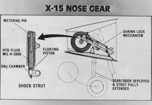
Figure 17. X-15 nose gear installation.


One of the biggest problems during the NAA testing portion of the program occurred during the ground testing of the large engine, the XLR-99, installed in the X-15 airframe. This occurred at Edwards Air Force Base at the thrust stand facility. We were running complete static tests on the aircraft with the large engine prior to its first flight. The X-15 was completely fueled, Crossfield was in the cockpit, the canopy closed, all the test engineers were in the blockhouse, a situation that could make the pilot feel expendable, and all instrumentation had been installed and was checked out. The test director gave the pilot the go-ahead, and Scott proceeded to start the engine and advanced the throttle to a high thrust, then lowered the power. This was repeated several times. On about the second or third time, there was a tremendous explosion. The cockpit moved about 20 ft forward, the aft fuselage and tankage disappeared, and flames enveloped the whole area. While the flames were still roaring around, one of the ground crew members got Scott out of the cockpit, and fortunately with no personal injury to either party. At this point, I was very glad that we had a nitrogen cockpit pressurization and cooling system. Had we employed oxygen, we would no doubt have also lost one pilot, one crew member, and a cockpit. There were thoughts on the why's of this accident involving valves and regulators that we had been having so much trouble with; however, one of the large contributors was the overboard ammonia line. To keep ammonia fumes out of the area, the ship's overboard system was connected into the underground water tank to absorb the fumes. However, the ship's system came directly from the regulator through a vent line to the outside of the aircraft, which in turn was connected to a hose that went into the disposal water tank. The ambient outside pressure that controlled the relief valve was also in the ship's overboard system; this should have been noted. The final result was to increase the back pressure which in turn increases pressure that the relief valve senses as ambient. Other than some redesign work on the ammonia tank valves to increase their reliability, the major change that occurred, as I am told, was to not use the water ammonia disposal system, thus taking the back pressure off the relief valve.

Even the last NAA flight had some rather trying moments in being accomplished. In December 1960, Crossfield was to make the last company flight. The X-15 had an XLR-99 engine installed that had seen some testing and was losing some of its Rokide insulation on the nozzle.

General Marcus Cooper, the commander of the Edwards Flight Test Center, called a meeting in his conference room. The subject was to be the XLR-99 engine and the Rokide material used to insulate the thrust chamber. The problem that had surfaced on this last flight was the amount of insulating material that had been lost. And with very limited experience with these engines, was the engine in a safe state for Scott to make this flight, or should the powerplant be changed?

The meeting had all the interested parties such as the factory representatives of the engine manufacturer, NASA, Scott Crossfield, NAA, and NASA propulsion experts, the launch director, and me. We were given a briefing by the engine company on what they had determined in their test program, and opinions from most of the other attendees. After a bit, General Cooper invited Scott and me into his office.

During this session, he questioned Scott on how he felt about flying the current configuration. Scott did not show any concern and indicated he was very willing to go ahead with the flight. After a few other questions, he excused Scott.

When we were alone, General Cooper asked my opinion, I told him that earlier this day on my arrival at Edwards that I had inspected the thrust chamber in question and did not have any great concerns. Yes, some of the insulation was gone, but not to any great extent and the individual areas were small. It had not all been lost in one area, but the loss was fairly evenly well distributed over the entire area. Further, it certainly had not caused any negative comments from the manufacturer or their test engineers. The General's comment was, "Very well, we will make it a joint decision to proceed with the flight." Needless to say, the flight went perfectly. And, I might add, this is very powerful evidence that no matter what, you can't always be wrong! Seriously, there is a point to be made here. That is, there is a very fine line between stopping progress and being reckless. That the necessary ingredient in this situation of solving a sticky problem is attitude and approach. The answer, in my opinion, is what I refer to as "thoughtful courage." If you don't have that, you will very easily fall into the habit of fearful safety and end up with a very long and tedious-type solution at the hands of some committee. This can very well end up giving a test program a disease commonly referred to as "cancelitis," which results in little or no progress and only creates another "Hangar Queen."

I would like to take a short review of some of the management facets that occurred before and during this program, beginning with when NAA submitted its bid on the X-15 program.

My position at that time was that of manager of research and development for the Los Angeles Division. Almost as soon as it was announced that we were the successful bidder, I was informed that top corporate management wanted to reject the program since it was small and they were concerned that too many of the top engineering personnel would be absorbed on this program and not be available for other projects that they considered more important to the future of the corporation. There was considerable objection to this position in the technical area. I was finally called in to Mr. Rice's office, the then chief engineer, and told that we could have the program on the condition that none of the problems were ever to be brought into his office. He further elaborated that it would be up to me to seek all the solutions and act as the top NAA representative for the program. This was fine with me. I felt that the X-15 program was vital to the future of aerospace and I wanted to be intimately involved with the future of this industry and would have no hesitation in agreeing to do most anything in order to be associated with the X-15 program. The big advantage I noted in this arrangement was that since it had been deemphasized in the corporation at the moment, we would have considerably fewer casual people attempting to modify this project so that they could boast and hopefully make some brownie points at the expense of this project. Things returned to the normal business, and after about 6 or so months, Mr. Rice was advanced to division president and a fair period after that I was appointed as chief engineer of the Los Angeles Division.

Soon after the contract award, we began interacting with the NASA in technical meetings. I insisted that the NAA team members stay in their own field of responsibility and not attempt to run each other's area of expertise. Hartley agreed with that approach and enforced a similar restriction on his associates. Also, he insisted on small, but frequent, meetings. I don't recall any meetings that had more than a total of 10 or 12 attendees. Surprisingly, we managed to get much accomplished, and we all left the meetings with a good concept of what had to be completed and when.

Another facet of the program that was on the positive side was that neither the NASA nor NAA found it necessary to import any new high-powered help from other fields or industries that lacked hands-on experience in this industry to serve as managers or directors. The whole team was veteran in the business. Further, there was a great spirit of understanding and cooperation.

Before I finish, I feel it is important to mention those members of the NAA team that in my opinion worked on the X-15 program with complete brilliance and dedication. My list is as follows: Chief Project Engineer Charles Feltz; Assistant Project Engineers Bud Benner and Ron Robinson; Power Plant Engineer Bob Fields; Regulators and Relief Valves Expert John Gibb; Chief of Aerodynamics Larry Greene; Project Aerodynamicist Bill Johnston. The remaining two individuals who are very outstanding in my mind are Scott Crossfield and Al White. Crossfield had flown the X- I and D-55 8 and left the government to fly the X- 15. He desired to participate in the complete program; however, this ended up as not being possible. Unfortunately, he was restricted to relatively low speeds of M = 2 to 3. There were many who thought he would break this restriction; knowing Scott, I knew that would never happen as he is a very dedicated professional test pilot and a man of his word. Several years before the flight operations started, he worked very diligently with the engineering group to ensure we designed in the maximum flight safety and to learn in complete detail how each of the subsystems operated. This knowledge was of extreme value to the program in the early debugging flights. Al White went through all the required training to be the backup pilot to Crossfield and trained for several years and was not even allowed one flight; that's dedication! I would like to call attention again that when all is said, Hartley Soule was the glue that held this project in line. Any organization can use people with his gift of technical competence and gentlemanly persuasiveness. For myself, I always admired Hartley SouI6 and enjoyed his company.

I have been very proud and pleased to be associated with this project and those who participated. They were all excellent, dedicated people. And I am certain that the participants are all very proud of the fact that the NASA has declared the X-15 the most successful research airplane project they have ever had, and I guess that record still stands.

Now the last figure, number 18, which is self explanatory and gives the highlights of the X-15 history.

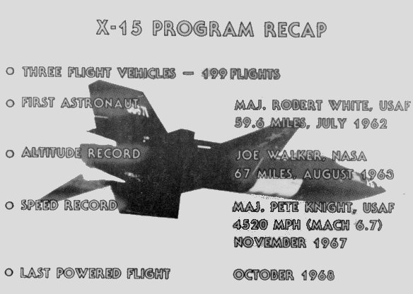
Figure 18. X-15 program recap.


At this point I would like to thank you for your attention.

QUESTIONS AND ANSWERS

(Audience)
How much were digital computers used in the X-15 design and simulation?

(Storms)
A tremendous amount. We had an iron bird that had all of the hydraulics in it, with all the control systems on the computer. We had two sets of computers: the first set was analog. Finally we got digital computers and put them there and it seemed to work out pretty well. I don't think we could have done it more completely even though we thought we were doing it completely at the time.

(Audience)
The subject is speed brakes. You haven't mentioned anything about your thoughts about why you put the speed brakes on the X- 15. 1 had the good fortune to do a lot of flight planning, and speed brakes came to be a very useful device for lots of different things all the way out to the highest Mach number flights. We're having trouble getting the X-30 designers to appreciate the significance of a device of this type.

(Storms)
I'm not exactly sure at this point. Do you remember, Walt?

(Williams)
I think as much as anything it was for modulation of L/D. Energy management.

(Storms)
It's primarily an operational aid. It doesn't cost all that much to put it on, so why not put it on and have it there? We even had speed brakes on the Sabreliner.