| Robert G. Hoey |
| Robert G. Hoey |
| |
| Figure 1. X-15 contributions to the X-30. |
| |
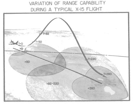
| Figure 2. Variation of range capability during a typical X-15 flight. |
| |
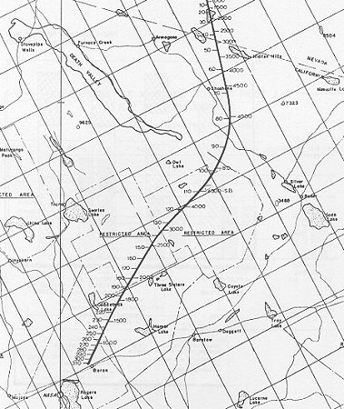
| Figure 3. Flightpath of the X-15 aircraft for heating test. |
| |
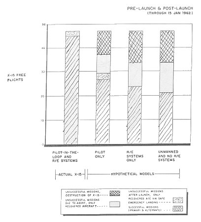
| Figure 4. Total pilot-in-the-loop and R/E systems benefit. |
| |
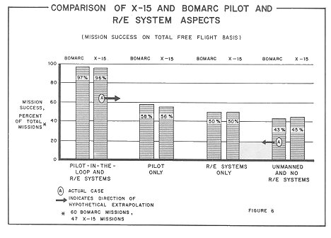
| Figure 5. Comparison of the X-15 and BOMARC pilot and R/E system aspects. |
| |
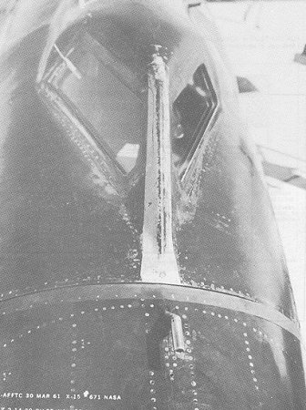
| Figure 6. Inconel deflector strip riveted forward of the canopy joint. |
| |
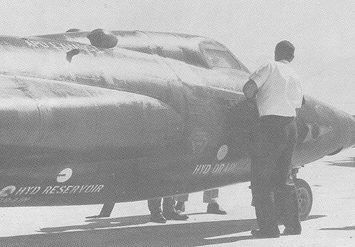
| Figure 7. Small spanwise buckles and local scorching observed in X-15's skin. |
| |
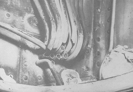
| Figure 8. Heat damage to the X-15's aluminum tubing. |
| |
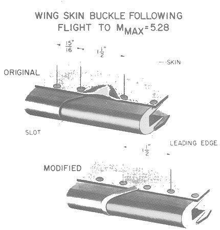
| Figure 9. Wing skin buckle following flight to Mmax=5.28. |
| |
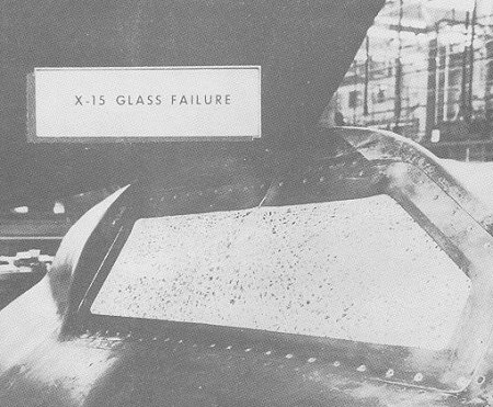
| Figure 10. X-15 glass failure. |
| |
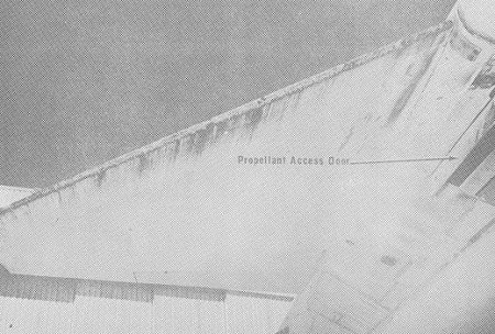
| Figure 11. Ablative wear lower fuselage and wing. |
| |
| Figure 12. Ablative wear wing leading edge. |
| |
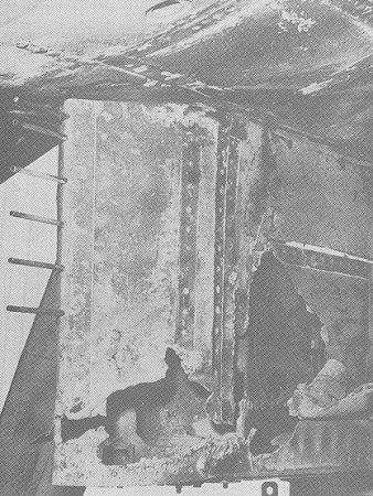
| Figure 13. Pylon heat damage, left side. |
| |
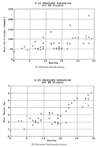
| Figure 14. X-15 envellope expansion for first 45 flights. |
| |
| Figure 15. Simultaneous development of a new airframe and a new propulsion system. |
 |
 |
 |