Tutorial: Plastic recipient The example to follow cover two very important commands: Create ULoft Surface and Create Blend Surface. For who already knows NURBS in programs like Rhino and Softimage it is important to know that the command Create Blend Surface from Max r2 just works with surfaces NURBS. Therefore, when it models an object that it should be taken into account and to plan the model with loft or starting from a primitive standard. Step 1) Creating shapes
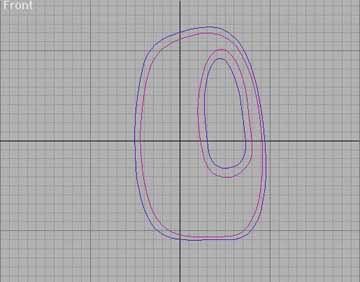
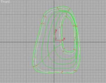
figure 1
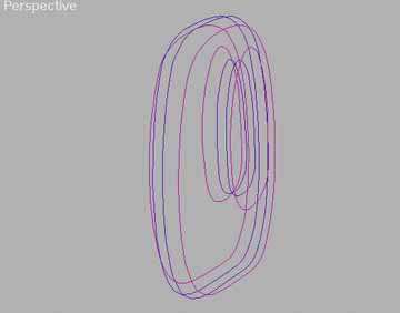
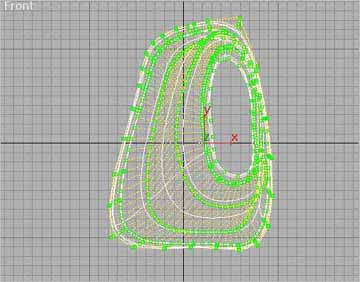
figure 2 Starting from the menu CREATE -> SHAPE chooses NURBS you Curve -> Point Curves. You should draw 2 basic shapes with the opening in ellipse form. The internal shape should be attached to the external shape. For that, enter in MODIFY PANEL to tie the two shapes (figure 1) that will just form a curved NURBS. Soon after, click in EDIT STACK and choose convert to: NURBS surface, and again use attach to tie all the lines. Type <S> to turn on Snap, because it is important that the distance among the shapes is the same, it will maintain the symmetry of the object and its control vertexes ( figure 2). Step 2) Using Create Uloft Surface
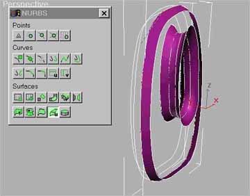
figure 3 With the selected shapes it calls Mofify Panel -> NURBS CREATION TOOLBOX ( figure 3) and click in the icon ULoft. Click in the first shape (the sharpener of the mouse becomes a cross) and soon after in the next corresponding shape. You should make this for external and internal shapes, that later help to form the hole. Step 3) Using Create Blend Surface
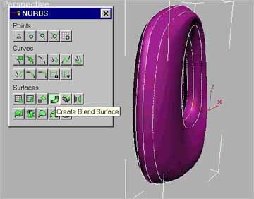
figure 4 Still in NURBS CREATION TOOLBOX, click in Blend Surface. You will notice that should just apply Blend in the lateral shapes. Give the first click in the external ellipse from shape and the second in the ellipse it interns, creating the faces and closing the object as showed the ( figure 4 ). In the Viewport configuration, choice force 2-sided, because the normal can be inverted, harming the visualization. Step 4) Moving points
figure 5
figure 6 There is two ways to edit object:
Step 5) Creating the screw-cap
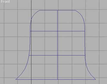
figure 7
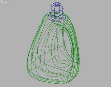
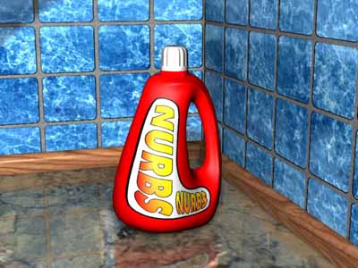
figure 8 In the menu CREATE -> Standard Primitives creates a cylinder and transform it in NURBS for MODIFY -> Edit Stack. Soon after, edit control vertexes as shown in the ( figure 7 ) and position the Cylinder (screw-cap) in the superior position, centralizing it. The grooves of the cover and the label are textures with bump map. I hope to have collaborated so that the subject NURBS is better understood. mailto:koyanagi@prudenet.com.br |